

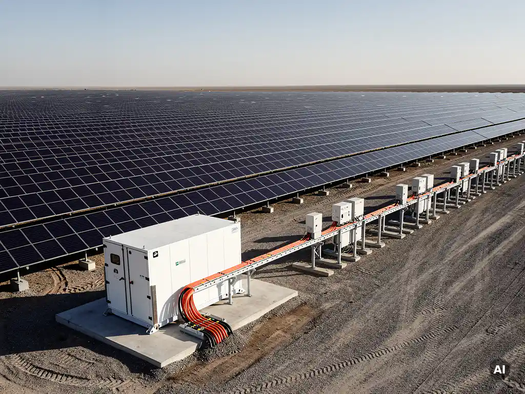
Engineering battery storage for a ground-mount solar plant means integrating an energy storage system with your PV array to shift generation, stabilize output, and meet grid requirements. The core decisions involve coupling architecture (DC or AC), battery sizing relative to your solar capacity, and how storage affects your inverter configuration and interconnection obligations. This article walks through each of those engineering questions in detail.
What components make up a ground-mount solar-plus-storage system?
A ground-mount solar-plus-storage system combines a photovoltaic array with a battery energy storage system (BESS) and the power electronics that connect them. The main components are the PV modules, mounting structure, inverters, battery modules with a battery management system (BMS), a plant controller, and the grid interconnection equipment, including transformers and protection relays.
Each component plays a distinct role in system performance. The PV array generates DC power, which flows through string or combiner boxes before reaching the inverter. The battery system stores excess generation and releases it on demand. The BMS monitors cell voltage, temperature, and state of charge to protect battery health and prevent unsafe operating conditions.
At the plant level, an energy management system (EMS) or plant controller coordinates dispatch between the solar array and the battery, following either a pre-programmed schedule or real-time grid signals. Protection and metering equipment at the point of interconnection ensures the plant meets utility requirements for fault protection, anti-islanding, and revenue-grade measurement.
- PV array: Modules, racking, string wiring, and combiner boxes
- Inverters: String or central inverters (or hybrid inverters in DC-coupled designs)
- Battery system: Battery modules, racks, BMS, and thermal management
- Plant controller / EMS: Dispatch logic and grid signal response
- Interconnection equipment: Transformers, switchgear, protection relays, and metering
What’s the difference between DC-coupled and AC-coupled battery storage?
The key distinction is where the battery connects in the power flow. In a DC-coupled system, the battery connects on the DC side of the inverter, before conversion to AC. In an AC-coupled system, the battery has its own dedicated inverter and connects on the AC side, after the solar inverter has already converted the power.
DC-coupled storage
DC coupling uses a hybrid inverter or a shared DC bus to connect the battery directly to the solar array’s DC output. Because the energy only passes through one conversion stage before reaching the grid, DC-coupled systems tend to have higher round-trip efficiency. This architecture is particularly well-suited to new-build projects where the inverter and battery are specified together from the start. The trade-off is less flexibility: the battery capacity and charge rate are constrained by the inverter’s DC input specifications.
AC-coupled storage
AC coupling adds a separate battery inverter on the AC bus, which means the battery can charge from both the solar array and the grid independently. This makes AC coupling the preferred choice for retrofitting storage onto an existing solar plant, since you do not need to replace or modify the existing inverters. The additional conversion stage does introduce slightly more conversion loss, but the operational flexibility and simpler integration with existing infrastructure often outweigh that difference on larger utility-scale projects.
How do you size a battery storage system for a solar plant?
Battery storage sizing for a solar plant starts with defining the use case, because the required energy capacity and power rating depend entirely on what the battery is expected to do. Common use cases include peak shaving, time-of-use shifting, frequency response, and self-consumption optimization. Each use case drives a different sizing methodology.
For time-shifting applications, you calculate the volume of energy you want to move from the generation window to the discharge window. If your plant generates surplus power for four hours at an average of 2 MW above the grid export limit, you need at least 8 MWh of usable capacity to capture that energy. Usable capacity is not the same as nameplate capacity: most lithium iron phosphate (LFP) batteries are sized with a depth of discharge (DoD) of around 80 to 90 percent, so nameplate capacity must be sized accordingly.
For power-based applications like frequency response or demand charge management, the power rating in megawatts matters more than energy capacity. A frequency response contract might require the battery to deliver a specific MW output for only 15 to 30 minutes, meaning a high power-to-energy ratio is more important than a large energy reservoir.
Degradation is a critical sizing input that is often underestimated. Battery capacity declines over the project lifetime, typically by 20 to 30 percent over 10 years depending on chemistry and cycling frequency. Sizing must account for end-of-life capacity so the system still meets contractual obligations in year 10 or year 15, not just at commissioning.
How does battery storage affect inverter sizing and DC/AC ratio?
Adding battery storage changes the inverter sizing calculation because the inverter must now handle both solar generation and battery discharge simultaneously, or, in some configurations, charge the battery from the grid. This means the inverter’s AC output rating must be evaluated against the combined peak power flow, not just the solar array’s output alone.
In DC-coupled designs, the hybrid inverter’s DC input capacity must accommodate both the PV array and the battery charge current. This can constrain how aggressively you clip the DC/AC ratio, since the inverter is already handling a larger DC input range. A DC/AC ratio that works well for a solar-only plant may need to be revisited when battery charging adds to the DC-side load.
In AC-coupled designs, the solar inverter and battery inverter are sized independently, which gives more flexibility. However, the point of interconnection and the transformer must be rated for the combined AC output of both inverters during simultaneous discharge. Engineers sometimes overlook this when retrofitting storage, leading to transformer overloading or interconnection limit violations.
Grid export limits add another layer of complexity. If the interconnection agreement caps export at a fixed MW level, the plant controller must coordinate solar curtailment and battery dispatch to stay within that limit. This affects how you size both the inverter and the battery, since the battery may need to absorb curtailed solar energy rather than letting it go to waste.
What grid interconnection requirements apply to solar-plus-storage plants?
Grid interconnection requirements for solar-plus-storage plants are more complex than for solar-only systems because the battery can both import and export power, which changes the plant’s behavior from the grid’s perspective. Most utilities and grid operators require a separate interconnection study that accounts for the storage system’s bidirectional power flow.
Key requirements typically include anti-islanding protection, reactive power capability, ramp rate control, and frequency and voltage ride-through settings. Storage adds the need to specify operating modes clearly in the interconnection agreement: whether the battery can charge from the grid, whether it can export independently of the solar array, and what happens during grid disturbances.
In many markets, the interconnection application must declare the maximum import and export capacity of the combined system. If the battery can charge from the grid, the import capacity affects the required protection settings and potentially the capacity of the interconnection infrastructure. Some utilities require a separate meter for the battery system to distinguish solar generation from storage dispatch for settlement and incentive purposes.
Compliance with grid codes such as IEEE 1547 in North America or the relevant national grid code in Europe is mandatory. These standards define voltage and frequency operating ranges, response times, and the conditions under which the plant must disconnect or ride through disturbances. Storage systems must be programmed and tested to meet these requirements before energization.
What are the most common engineering mistakes in solar storage design?
The most common engineering mistakes in solar-plus-storage design fall into three categories: undersizing for degradation, mismatching the coupling architecture to the use case, and failing to model the combined power flows through shared equipment like transformers and switchgear.
Undersizing for degradation is the most financially damaging mistake. Engineers who size the battery to meet performance requirements at commissioning often find the system falls short of contracted obligations within a few years as capacity fades. Always size to end-of-life capacity and validate the degradation assumptions with the battery manufacturer’s warranty data.
Choosing the wrong coupling architecture creates problems that are expensive to fix after construction. DC coupling on a retrofit project forces inverter replacement; AC coupling on a new-build project adds unnecessary conversion losses and equipment costs. The coupling decision should be made early in the design process, with the use case and project timeline as the primary inputs.
Overlooking shared equipment ratings is a frequent source of late-stage design revisions. When the battery inverter and solar inverter can both export simultaneously, the transformer, switchgear, and interconnection cables must be rated for the combined peak output. Running a power flow analysis that models simultaneous solar and battery discharge is essential, not optional.
Other common mistakes include:
- Failing to account for auxiliary loads (cooling, BMS, controls) in the energy balance
- Ignoring thermal management requirements, which affect both battery performance and enclosure sizing
- Specifying protection settings without coordinating with the utility’s interconnection requirements
- Omitting a detailed EMS dispatch strategy, leaving the battery operating on default settings that do not match the project’s revenue model
Getting these details right from the start is what separates a project that performs as modeled from one that underdelivers. If you are working through the engineering on a ground-mount storage project and want to explore how purpose-built solar design software can reduce the risk of these errors, or if you want to discuss your specific project requirements, our team is happy to help. You can reach out directly to talk through your design challenges.
Frequently Asked Questions
Can a ground-mount solar-plus-storage system qualify for both the Investment Tax Credit (ITC) and battery-specific incentives?
Yes, but eligibility depends on how the battery is charged. Under current U.S. federal rules, a battery qualifies for the ITC if it is charged at least 75% from the co-located solar array. If the battery charges from the grid, only the solar-charged portion may qualify. Always consult a tax advisor familiar with energy storage incentives, and ensure your EMS dispatch strategy is configured to maintain the required solar-charging ratio if ITC eligibility is a project priority.
What battery chemistry is best suited for utility-scale ground-mount solar storage projects?
Lithium iron phosphate (LFP) is currently the dominant chemistry for utility-scale solar-plus-storage projects due to its favorable cycle life, thermal stability, and declining cost per kWh. NMC (nickel manganese cobalt) offers higher energy density but carries greater thermal runaway risk, making it less common in large ground-mount applications. For projects with very high cycle requirements — such as daily time-shifting over a 15-year project life — LFP’s superior cycle durability typically makes it the more cost-effective choice over the project lifetime.
How do I determine the right power-to-energy (P/E) ratio for my storage system?
The right P/E ratio is driven directly by your primary use case. Frequency regulation and fast-response ancillary services typically require a high P/E ratio (e.g., 1C or higher), meaning a 1 MW system with just 1 MWh of capacity. Time-shifting and peak shaving applications generally call for a lower P/E ratio, such as a 2- to 4-hour duration (0.25C to 0.5C), where a 1 MW system would pair with 2–4 MWh of storage. If your project targets multiple revenue streams, model each use case separately and size to the most demanding one, then validate that the battery can handle the combined cycling profile.
What happens to the battery system during a grid outage — can it keep the solar plant running?
This depends on whether the system is designed for islanding capability, which is a specific design and permitting decision, not a default feature. Most utility-scale solar-plus-storage plants are configured to disconnect from the grid during an outage (anti-islanding protection) and will not continue operating. To enable islanding or black-start capability, the inverter and protection system must be explicitly designed and approved for that mode, and the interconnection agreement must permit it. If resilience or backup power is a project requirement, it must be defined early in the design process, as it affects inverter selection, protection settings, and interconnection negotiations.
How should I approach the EMS dispatch strategy if my project has multiple revenue streams?
Start by ranking your revenue streams by priority and contractual obligation — for example, a frequency response contract with strict availability requirements should take precedence over opportunistic time-of-use arbitrage. Your EMS should be programmed with a clear hierarchy of dispatch modes and the conditions under which each activates. Work with your EMS vendor to model realistic dispatch scenarios using historical solar generation and grid price data, and validate that the battery’s state of charge is managed to always meet your highest-priority obligation. Avoid relying on default EMS settings, as these are rarely optimized for a specific project’s revenue model.
At what project scale does it make sense to use a central inverter versus string inverters in a solar-plus-storage system?
String inverters are generally preferred for projects up to around 5–10 MW because they offer module-level flexibility, easier maintenance, and better partial-shading performance. Central inverters become more cost-competitive at larger scales (typically 10 MW and above) due to lower cost per watt and simpler high-voltage AC collection. For storage integration specifically, string inverter architectures can simplify DC coupling by pairing individual inverters with battery units, while central inverter designs often use a shared DC bus or AC coupling. The right choice depends on your project size, site layout, and whether you are prioritizing upfront cost or long-term operational flexibility.
What documentation should I prepare before submitting a solar-plus-storage interconnection application?
Before submitting, you should have a completed single-line diagram showing both the solar and battery systems, the maximum import and export capacity of the combined plant, inverter and battery specifications (including IEEE 1547 compliance documentation), proposed protection relay settings, and a description of the battery’s operating modes — particularly whether it will charge from the grid. Many utilities also require a power flow study or short-circuit analysis as part of the application package. Engaging with the utility’s interconnection team early, before finalizing your design, can prevent costly revisions later if the utility has specific technical requirements that affect your equipment selection.
Related Articles
This content was generated with the help of AI — it may contain mistakes
Source link