

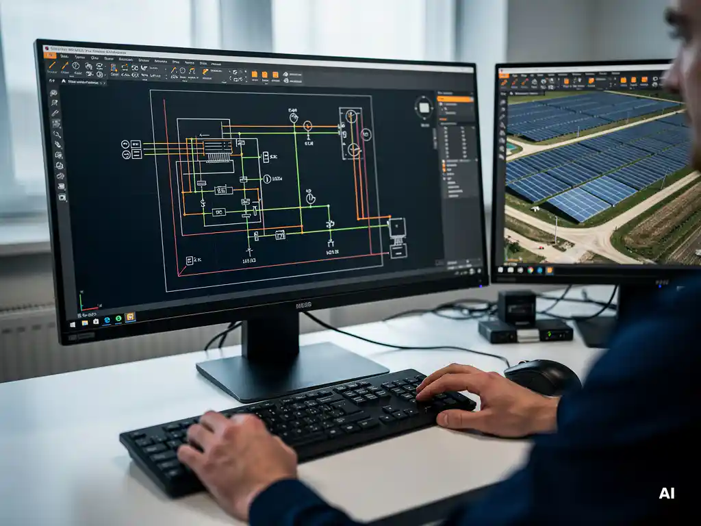
Several solar design tools can generate automatic single-line diagrams (SLDs), including Virto.CAD, AutoCAD-based plugins, and dedicated PV engineering platforms. The best options build the solar wiring diagram directly from your project data, eliminating the need to draw connections manually. Below, we break down how these tools work, which projects benefit most, and what to look for in a construction-ready output.
How does automatic SLD generation actually work in solar software?
Automatic SLD generation works by reading the electrical parameters already defined in your project, such as string configurations, inverter specifications, combiner box assignments, and cable sizing, and then translating that data into a standardized wiring diagram without manual drafting. The software uses the project’s logical structure as the source of truth, so the diagram reflects the actual design rather than a manually redrawn interpretation of it.
In practice, this means that once an engineer has completed inverter sizing, string planning, and equipment selection, the SLD is essentially ready to be produced. The software maps each string to its corresponding input, routes connections through protection devices, and labels components according to the project’s bill of materials. Because the diagram is generated from live project data, any change to the design, such as swapping a module type or adjusting string length, automatically propagates into the updated diagram.
This is a significant departure from the traditional workflow, where engineers would complete their calculations in spreadsheets and then manually redraw the SLD in AutoCAD. That two-step process introduced transcription errors and made revisions time-consuming. Automatic generation collapses both steps into one, keeping the wiring diagram synchronized with the engineering model at all times.
What types of solar projects benefit most from automated SLDs?
Commercial, industrial, and utility-scale solar projects benefit most from automated SLD generation. These are the project types where electrical complexity is highest, revision cycles are most frequent, and the cost of errors in the wiring diagram is greatest. Large ground-mounted systems with multiple inverters, combiner boxes, and cable runs are particularly well suited because the number of connections that need to be documented grows quickly with system size.
Rooftop C&I projects also benefit significantly. While they may be smaller in scale than utility installations, they often involve complex roof geometries, multiple sub-arrays, and tight permitting requirements that demand precise, legible documentation. Automated SLDs ensure that the diagram submitted for approval accurately reflects the installed design, reducing the risk of permit rejections or inspection failures.
Smaller residential installations can also use automated SLD tools, but the time savings are proportionally less dramatic because the electrical topology is simpler. The strongest return on investment comes from projects where the engineering team would otherwise spend hours or days drafting and revising diagrams manually, which is firmly in the C&I and utility-scale territory.
Which tools generate automatic SLDs for solar projects?
Several tools on the market can generate automatic SLDs for solar projects, ranging from standalone PV design platforms to CAD-integrated plugins. The right choice depends on your project type, your existing design environment, and how deeply the SLD needs to integrate with the rest of your engineering documentation.
CAD-integrated plugins
For engineering teams already working in AutoCAD or BricsCAD, a CAD-integrated plugin is often the most practical option because it keeps the entire workflow inside a familiar environment. Virto.CAD is one example: it automates string planning, cable sizing, and SLD creation directly within the CAD workspace, so the wiring diagram is produced as part of the same project file rather than as a separate document. This tight integration means that layout changes automatically feed into the electrical diagram without switching tools or re-entering data.
Standalone PV design platforms
Web-based PV design platforms such as PVsyst, Helioscope, and similar tools offer varying degrees of SLD automation. Some generate schematic-level diagrams suitable for energy modeling and early-stage design, while others produce more detailed outputs intended for permitting. The trade-off is that these platforms typically operate outside the CAD environment, which means the SLD may need to be exported and reformatted before it can be incorporated into a full construction drawing set.
Electrical design software
General electrical design tools such as ETAP or SKM can produce highly detailed SLDs and are sometimes used for utility-scale interconnection studies. However, they are not purpose-built for PV systems, which means engineers often need to build custom templates and component libraries before the tool can generate a solar-specific wiring diagram efficiently.
What should an automatically generated SLD include to be construction-ready?
A construction-ready solar wiring diagram must include every element that an installer, inspector, or commissioning engineer needs to verify the system without referring back to separate calculation sheets. At minimum, this means string configurations with module counts, inverter connections with input channel assignments, protection device ratings, cable cross-sections and lengths, and clear labeling of all major components referenced in the bill of materials.
Beyond the basic topology, a construction-ready SLD should also include:
- DC and AC circuit protection devices with rated values
- Grounding and bonding connections
- Combiner box or string combiner assignments where applicable
- Meter and monitoring connection points
- Disconnect switch locations
- Voltage and current values at key points in the circuit
- Equipment model numbers and ratings consistent with the project specification
A diagram that omits any of these elements forces the installer or inspector to cross-reference other documents, which increases the risk of misinterpretation and slows down the commissioning process. The value of automatic SLD generation is not just speed but accuracy: because the diagram is drawn from the project’s own data, the values shown on the diagram match the values in the calculations, eliminating the discrepancies that commonly appear when diagrams are drawn manually after the fact.
How much time does automatic SLD generation save compared to manual drafting?
Automatic SLD generation can reduce the time spent producing a solar wiring diagram from several hours or even days to a matter of minutes. For a mid-size commercial project, manually drafting an SLD in AutoCAD, including labeling, checking against calculations, and revising after design changes, can easily consume a full working day or more. Automated generation compresses that to the time it takes to review and approve the output.
The savings compound significantly across a project’s revision cycle. In a typical C&I or utility-scale project, the design goes through multiple rounds of changes driven by equipment availability, client feedback, or site conditions. Each revision that affects the electrical design requires the SLD to be updated. With manual drafting, every update is a fresh drafting task. With automatic generation, the updated diagram is produced as soon as the underlying project data changes.
Industry experience with tools like Virto.CAD points to overall engineering time reductions of around 80% when automation covers the full workflow from string planning through SLD creation. Even if SLD generation alone accounts for only a portion of that saving, the cumulative effect across multiple projects in a year represents a substantial capacity gain for an engineering team. If you want to see how that plays out in your own workflow, you can speak with our team about a hands-on evaluation.
Frequently Asked Questions
Can automatic SLD generation tools handle hybrid solar systems with battery storage?
Most modern PV design platforms and CAD-integrated plugins like Virto.CAD are increasingly adding support for hybrid system configurations that include battery energy storage systems (BESS). However, the level of detail varies by tool — some will automatically incorporate the inverter-battery interface and protection devices into the SLD, while others may require manual additions for storage-side components. If your projects regularly include storage, it’s worth confirming with the software vendor that their SLD output covers DC-coupled or AC-coupled battery connections before committing to a platform.
What happens to the SLD if I change equipment mid-project, such as swapping to a different inverter model?
With automatic SLD generation, swapping a major component like an inverter model triggers an automatic update across the diagram — new input channel counts, updated ratings, and revised labeling are all reflected without manual redrafting. This is one of the most practical advantages over traditional workflows, where an equipment change would require the engineer to manually hunt down and correct every affected element in the drawing. The key requirement is that the new equipment’s specifications are already loaded into the software’s component library; if they aren’t, you may need to add the component data before the diagram can update correctly.
Are automatically generated SLDs accepted by permitting authorities and utilities?
In most jurisdictions, permitting authorities and utilities evaluate SLDs based on their content and accuracy rather than how they were produced, so an automatically generated diagram that meets the required documentation standards is fully acceptable. The critical factor is that the output includes all required elements — protection device ratings, cable sizing, voltage and current values, equipment model numbers, and proper labeling — which a well-configured automatic tool will handle by default. If you’re working in a jurisdiction with specific formatting or stamp requirements, verify that the tool’s output can be exported in a compatible format and that your licensed engineer can apply their seal to the final document.
What are the most common mistakes engineers make when first adopting automated SLD tools?
The most frequent mistake is treating the automatically generated SLD as final without performing a thorough review, assuming that automation eliminates the need for engineering judgment. While the diagram accurately reflects the project data, errors in the upstream design — such as incorrect string sizing inputs or missing protection device assignments — will propagate directly into the SLD. A second common pitfall is failing to populate the software’s component library with project-specific equipment data before generating the diagram, which can result in generic placeholders appearing where actual model numbers and ratings should be shown.
How do I get started with automatic SLD generation if my team currently drafts everything manually in AutoCAD?
The most practical starting point for teams already working in AutoCAD is a CAD-integrated plugin, since it allows you to adopt automation without abandoning your existing drafting environment or retraining your team on an entirely new platform. Tools like Virto.CAD work directly within the AutoCAD workspace, meaning your engineers can begin automating string planning and SLD creation on a single pilot project to evaluate the time savings before rolling it out across all projects. Before starting, audit your current workflow to identify which inputs — string configurations, inverter specs, cable sizing — the tool will need, and ensure that data is being captured in a structured format that the plugin can read.
Can automated SLD tools scale to very large utility-scale projects with hundreds of strings and multiple inverter blocks?
Yes, and in fact utility-scale projects are where automated SLD generation delivers its greatest value, since the sheer volume of connections, combiner boxes, and inverter blocks makes manual drafting both time-prohibitive and error-prone. Purpose-built PV design tools and CAD-integrated plugins are designed to handle large system topologies by organizing the diagram hierarchically — grouping strings into combiners, combiners into inverter blocks, and inverter blocks into the overall plant layout. For very large projects, it’s worth confirming that the tool supports multi-sheet SLD outputs and can segment the diagram into logical sections, such as separate sheets per inverter block, to keep the documentation legible and navigable for installers and inspectors.
Is it possible to customize the appearance and layout of an automatically generated SLD to match company or client standards?
Most professional-grade SLD tools offer a degree of customization, including control over title block content, component symbol styles, labeling conventions, and sheet formatting, so the output can align with your firm’s drawing standards or a client’s documentation requirements. CAD-integrated tools like Virto.CAD have a particular advantage here because the generated diagram lives inside the CAD environment, where engineers can apply standard CAD formatting, layer structures, and templates directly. The extent of customization varies by platform, so if brand consistency or client-specific formatting is a firm requirement, it’s advisable to request a sample output from the vendor before adopting the tool.
Related Articles
This content was generated with the help of AI — it may contain mistakes
Source link