

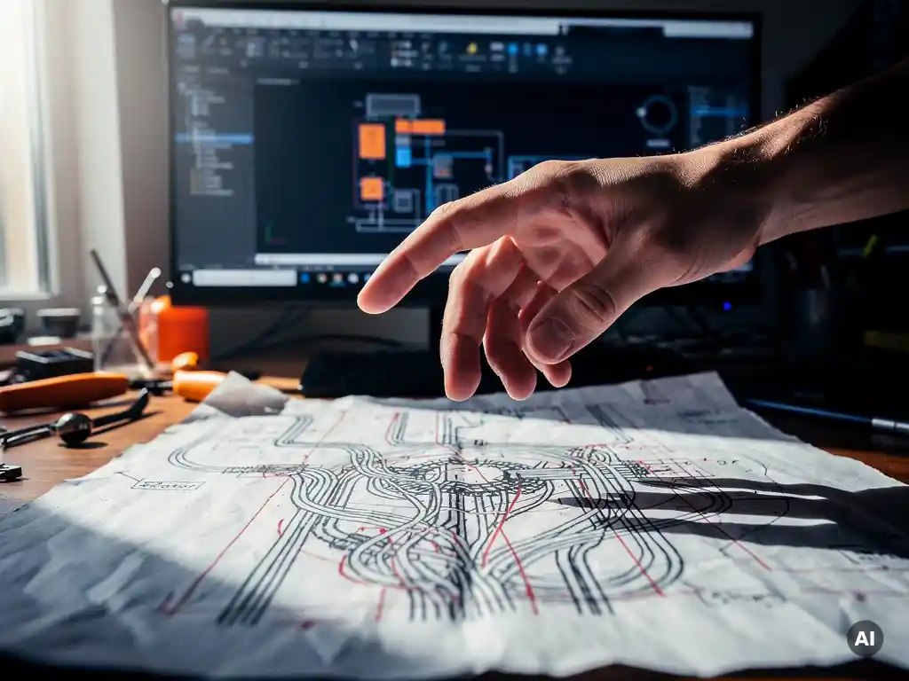
The most effective way to avoid errors when drawing solar wiring diagrams manually is to follow a structured, step-by-step verification process: check string configurations against inverter input limits, validate cable sizing calculations independently, and have a second engineer review the completed diagram before submission. Manual solar wiring diagrams are inherently error-prone because a single incorrect value cascades through every downstream calculation. The sections below break down where errors typically originate, how revisions amplify them, and when switching to automated tools becomes the smarter engineering decision.
What types of errors are most common in manual solar wiring diagrams?
The most common errors in manual solar wiring diagrams fall into three categories: incorrect string configuration (too many or too few modules per string relative to inverter voltage limits), cable sizing mistakes (undersized conductors that cause excessive voltage drop or thermal risk), and labeling inconsistencies (mismatched component references between the diagram and the bill of materials). These errors are easy to introduce and surprisingly hard to catch during review.
String configuration errors are particularly damaging. When an engineer manually calculates the maximum open-circuit voltage under low-temperature conditions and gets the arithmetic wrong, the resulting design may push the inverter beyond its rated input voltage. This kind of mistake often goes undetected until commissioning, where it can cause equipment damage or a failed inspection.
Cable sizing errors tend to cluster around DC trunk cables and combiner box connections, where current values are highest and the consequences of undersizing are most severe. Engineers working from memory or reusing old spreadsheet templates without updating the module specifications are especially vulnerable here.
Labeling and reference errors are the most common source of rework. A circuit breaker labeled CB-03 in the single-line diagram that appears as CB-3 in the panel schedule creates confusion during installation and can trigger costly site visits to reconcile the discrepancy. In large utility-scale projects with hundreds of strings, even a small inconsistency rate across labels produces a significant volume of errors.
Why do manual revisions make wiring diagram errors worse?
Manual revisions make wiring diagram errors worse because each update is applied in isolation rather than propagated automatically across the entire diagram. When a module specification changes, an engineer must manually update string voltage calculations, cable sizing, protection device ratings, and the single-line diagram itself. Each of these steps is a new opportunity to introduce an error or miss a dependency entirely.
This is one of the most frustrating realities of manual solar wiring diagram work. A project that has already been reviewed and approved can be thrown back into an error-prone state the moment a client requests a module substitution or the inverter manufacturer updates a datasheet. The engineer is essentially starting a new review cycle from scratch, but under time pressure and with the false confidence that the diagram is “mostly done.”
Version control compounds the problem. When multiple engineers are working on the same project, it is common for an updated diagram to be saved under a new filename while an older version continues to circulate. Reviewers may sign off on a diagram that has already been superseded, meaning the approved document does not reflect the current design intent. This disconnect between document versions and actual design decisions is a structural weakness of fully manual workflows.
What checks should a solar wiring diagram go through before submission?
Before submission, a solar wiring diagram should go through at least four verification checks: a string voltage and current validation against inverter specifications, a cable sizing and voltage drop review, a protection device coordination check, and a cross-reference audit between the diagram, the bill of materials, and any associated calculation sheets. Each check should be performed by someone other than the original drafter where project resources allow.
Electrical parameter validation
The first check confirms that every string in the design stays within the inverter’s maximum input voltage under worst-case temperature conditions, and that the combined string current does not exceed the maximum input current per MPPT channel. This check should use the module’s temperature coefficients from the actual datasheet, not generic assumptions. Errors here are the most likely to cause equipment failure in the field.
Cable and protection device review
The second check covers conductor sizing and protection coordination. Every cable run should be verified against the calculated short-circuit current, the installation method (conduit, tray, direct burial), and the maximum allowable voltage drop for that circuit segment. Protection devices, including fuses, circuit breakers, and disconnect switches, should be confirmed to match the fault current levels calculated for each point in the system. This review is best performed using a separate calculation sheet rather than relying solely on what is shown in the diagram itself.
Cross-reference and labeling audit
The third check is a line-by-line comparison between the wiring diagram and every other project document that references the same components. Every label, reference designator, and component identifier in the diagram should match exactly what appears in the panel schedule, the BOM, and the installation drawings. This audit is tedious but essential, and it is the step most often skipped under deadline pressure.
How does automated SLD generation reduce wiring diagram errors?
Automated single-line diagram generation reduces wiring diagram errors by eliminating the manual transcription steps where most mistakes originate. When a software tool generates the SLD directly from the engineering inputs, string configurations, cable sizing, and component selections are all reflected in the diagram automatically and consistently. There is no separate drawing step where values can be mistyped or omitted.
The deeper benefit is that automated SLD generation maintains consistency across the entire project document set. When a module specification changes, the software updates the string voltage calculations, the cable sizing, and the diagram simultaneously. Engineers do not need to track down every place a value appears and update it manually. This removes the revision-driven error cycle described earlier and makes late-stage design changes far less risky.
Our own Virto Solar platform handles exactly this through Virto.CAD, which generates construction-ready single-line diagrams automatically as part of the broader PV design workflow inside AutoCAD and BricsCAD. Because the diagram is produced from the same data that drives the string planning, BOM, and cable layout, the outputs are inherently consistent. Engineers who have used this approach report that the review process becomes substantially faster because the most common manual errors simply do not appear.
When should a solar engineer use software instead of drawing diagrams manually?
A solar engineer should use software instead of drawing wiring diagrams manually when the project involves more than a handful of strings, when design revisions are likely, or when the diagram must stay synchronized with other project documents like cable schedules and bills of materials. For any commercial, industrial, or utility-scale project, the complexity and revision risk of manual diagramming makes software the more reliable and time-efficient choice.
The practical threshold is lower than most engineers expect. Even a mid-size commercial rooftop with a dozen strings and two inverters generates enough interdependencies between string configuration, cable sizing, and protection device selection that manual tracking becomes unreliable. The risk is not that engineers lack the skill to draw accurate diagrams manually. The risk is that the volume of interdependent values exceeds what any individual can reliably track across multiple revisions under normal project timelines.
For large-scale ground-mount projects, the case for software is straightforward. Hundreds of strings, multiple combiner boxes, and complex DC collection networks produce a diagram that is simply too large to verify manually with confidence. Automated tools not only generate the diagram faster but also flag configuration errors before they reach the review stage, which is where catching mistakes is cheapest.
If you are evaluating whether your current workflow is creating unnecessary risk, speaking with our team is a practical starting point. We work with EPC firms and engineering consultancies at every scale and can help identify where manual diagramming is introducing the most exposure in your specific project types.
Frequently Asked Questions
How do I catch string voltage errors before they reach the commissioning stage?
The most reliable method is to build a dedicated string voltage calculation sheet that pulls directly from the module datasheet — specifically the open-circuit voltage (Voc) and its temperature coefficient — and applies the lowest expected ambient temperature for the project site. Run this calculation independently of the wiring diagram itself, then compare the results against the inverter’s maximum input voltage before the diagram is finalized. If the two sources disagree, the diagram is wrong. Catching this discrepancy at the calculation stage costs minutes; catching it at commissioning can cost days and significant equipment replacement expenses.
What is the safest way to manage module substitutions mid-project without introducing new errors?
Treat any module substitution as a full design reset for every parameter that depends on module specifications: Voc, Isc, power output, and temperature coefficients. Create a checklist that maps every downstream value affected by the module change — string voltage limits, cable sizing, fuse ratings, and BOM quantities — and work through it sequentially before updating the diagram. Never carry forward a previously approved diagram with only partial updates applied, as this is one of the most common sources of latent errors that survive review. If you are using automated design software, a module swap should trigger automatic recalculation across all dependent outputs.
How should version control be handled on projects where multiple engineers are editing the same wiring diagram?
Establish a single controlled master file with a clearly defined naming convention that includes the revision number and date, and designate one person as the document controller responsible for issuing and archiving each revision. Never allow engineers to work from locally saved copies without checking out the file from a shared, access-controlled location. A simple revision log embedded in the drawing title block — listing the change description, author, and approval date for each version — provides a traceable record that prevents reviewers from inadvertently signing off on a superseded document.
Are there specific project types where manual wiring diagrams are still acceptable?
Manual diagramming remains manageable for very small, simple systems — typically residential installations with a single inverter, one or two strings, and no complex protection coordination requirements. In these cases, the number of interdependent values is low enough that a careful engineer can track them reliably without software assistance. However, even for small projects, using a standardized template with locked calculation cells reduces the risk of template-reuse errors. As soon as a project involves multiple MPPTs, combiner boxes, or a BOM that must stay synchronized with the diagram, the risk profile of manual diagramming increases sharply.
What is the most common mistake engineers make when reusing wiring diagram templates from previous projects?
The most common mistake is updating the module and inverter labels on the diagram without recalculating the underlying electrical parameters — particularly string voltage limits, cable ampacity, and fuse ratings — for the new equipment. A template carries forward the values that were correct for the original project, and those values are often plausible enough to pass a casual review even when they are wrong for the new design. Always treat a reused template as a starting point for layout only, and independently verify every calculated value against the actual datasheets for the current project’s components.
How much time does automated SLD generation typically save compared to drawing diagrams manually?
Time savings vary by project scale, but engineers commonly report that automated SLD generation reduces diagram production time by 60–80% on commercial and utility-scale projects, with the largest gains coming from elimination of manual cross-referencing and revision cycles. The more significant efficiency gain, however, is in the review stage: because automated tools eliminate the most common transcription errors before the diagram is even drafted, review cycles are shorter and require fewer iterations. On projects with frequent design changes, the cumulative time saved across multiple revision rounds often exceeds the initial production time savings.
What should I look for when evaluating solar design software for wiring diagram generation?
Prioritize tools that generate the SLD directly from the same dataset used for string planning, cable sizing, and BOM production — this integration is what eliminates the transcription errors that manual workflows are prone to. Confirm that the software applies site-specific temperature conditions to string voltage calculations automatically and flags configurations that exceed inverter input limits before the diagram is finalized. Also evaluate whether the output format is compatible with your submission requirements, since construction-ready diagrams in standard CAD formats (such as DWG) reduce the risk of formatting errors introduced during file conversion or manual redrafting for client deliverables.
Related Articles
This content was generated with the help of AI — it may contain mistakes
Source link