

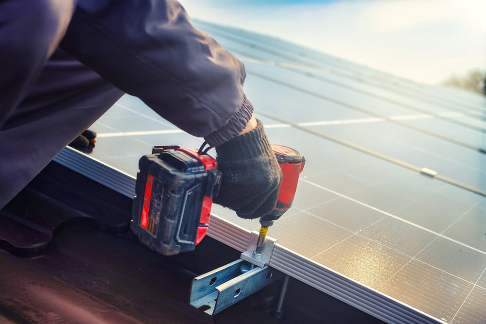
Solar panel grounding looks simple on the roof and gets complicated on the plan set. Solar grounding and bonding mistakes can lead to plan corrections, inspection comments, and return trips that eat into project margins.
This guide covers solar panel grounding requirements under NEC Article 690 and Article 250. You’ll find what NEC 690.43 requires, how to size the equipment grounding conductor, when PV system grounding calls for a ground rod, and how UL 2703 bonding works on real racking.
It’s written for solar installers and electrical contractors adding PV to their scope. For series and parallel configurations, conductor ampacity, and connector compliance, see the solar panel wiring guide for installers. This article stays focused on the grounding and bonding path.
Code adoption note: This guide references the 2023 edition of the National Electrical Code (NFPA 70) unless noted. Many AHJs still enforce the 2020 NEC, and the 2026 NEC is now published. The rules that apply are the ones your AHJ has adopted, so confirm the edition before finalizing a design.
Need grounding and bonding details on your next plan set? GreenLancer solar permit design delivers permit-ready plan sets with complete electrical, grounding, and bonding details. Sign up for free to start your next project.
What Are the Solar Panel Grounding Requirements?
Solar panel grounding requires exposed metal module frames, racking, enclosures, and other conductive PV equipment to be bonded and connected to an equipment grounding conductor (EGC). NEC 690.43 covers PV equipment grounding and bonding, 690.45 governs EGC sizing, and 690.47 addresses the connection to the grounding electrode system.
These sections build on the general rules in Article 250. Most DC PV circuits also need ground-fault protection, which is typically built into the inverter.
Here are the core requirements at a glance:
-
Bond the metal: Module frames, rails, enclosures, and metal raceways need an electrically continuous path (NEC 690.43).
-
Use listed bonding hardware: Devices that bond module frames must be listed, labeled, and identified for bonding.
-
Route the EGC correctly: Rules change once PV circuit conductors leave the vicinity of the array (NEC 690.43(C)).
-
Size the EGC: Use NEC 690.45 and Table 250.122.
-
Connect to a grounding electrode system: Follow NEC 690.47 and Article 250.
-
Provide ground-fault protection: DC PV circuits over 30 volts or 8 amps need ground-fault protection under NEC 690.41(B).
Solar Grounding and Bonding: What’s the Difference?
Bonding joins exposed metal parts into an electrically continuous fault-current path. The equipment grounding conductor connects that bonded equipment back toward the source so an overcurrent or ground-fault device can clear a fault. The grounding electrode system connects the electrical system to earth.
These three systems work together, but they aren’t interchangeable. A common misconception is that fault current needs to go “into the earth.” Earth is a poor fault-clearing path, and the EGC is what lets a protective device operate.
|
Bonding and bonding jumpers |
Connect metal parts so they form a continuous, low-impedance path |
|
|
Equipment grounding conductor (EGC) |
Carries fault current from bonded equipment back toward the source so the OCPD or ground-fault device can operate |
|
|
Grounding electrode conductor (GEC) |
Connects the system or equipment to a grounding electrode |
250.64, 250.66, 250.166, 690.47 |
|
Grounding electrode system |
Connects the electrical system to earth through rods, rebar, water pipe, or qualifying structures |
|
|
PV system grounding configuration |
Defines whether the PV system is functionally grounded, ungrounded, or solidly grounded |
Do Solar Panels Need to Be Grounded?
Yes. Under NEC 690.43, exposed non-current-carrying metal parts of PV module frames, electrical equipment, and conductor enclosures must be connected to an EGC regardless of voltage. That applies to small arrays, low-voltage DC systems, and microinverter systems alike.
What changes from project to project is how you create that path. Listed racking, bonding clamps, washers, lugs, and trunk cables with an integrated EGC are all ways to get there.
What About Microinverter Systems?
Microinverters don’t eliminate module frame and racking bonding requirements. Many current microinverters are double-insulated and don’t need their own grounding electrode conductor, but the module frames and rails still need a bonded path back to an EGC.
Check the microinverter spec sheet and installation manual. Some products provide the EGC through the AC trunk cable, while others require a separate conductor to the racking.
Does Solar Racking Need to Be Grounded?
Yes. Metallic racking is part of the bonded path whenever it supports PV modules or equipment. A racking system listed for bonding can serve as that path when installed per its instructions.
Racking that isn’t listed for bonding needs bonding jumpers between separate metallic sections. Either way, the racking must connect to the EGC.
NEC 690.43 Solar Equipment Grounding and Bonding Requirements
NEC 690.43 is the core solar panel grounding section. It tells you what must be connected to the EGC and which devices are allowed to do the bonding. In the 2023 NEC, it’s organized into subsections (A) through (D).
690.43(A): PV Module Mounting Systems and Devices
Devices and systems used to mount PV modules that also bond the module frames must be listed, labeled, and identified for bonding. Devices that mount adjacent modules are permitted to bond those modules to each other.
690.43(B): Equipment Secured to Grounded Metal Supports
Equipment such as inverters, optimizers, and junction boxes can be bonded through a grounded metal support when the bonding device is listed, labeled, and identified for that purpose. Where metal support sections are separate, bonding jumpers are required between them.
690.43(C): Equipment Grounding Conductor Location
The 2023 NEC clarified this rule into two parts. Within the PV array, EGCs can be run separately from the PV circuit conductors.
Once PV circuit conductors leave the vicinity of the array, the EGC must comply with 250.134. In practice, that usually means running it in the same raceway or cable as the circuit conductors. EC&M’s breakdown of NEC requirements for solar walks through each subsection with diagrams.
690.43(D): Bonding Over 250 Volts
The extra bonding requirements in 250.97 for circuits over 250 volts to ground don’t apply to metal raceways or metal cables containing PV system DC circuit conductors. This matters most on commercial and high-voltage string systems with metal conduit runs.
How to Size a Solar Equipment Grounding Conductor
Under NEC 690.45, the solar equipment grounding conductor size is based on Table 250.122 and the rating of the overcurrent device protecting the circuit. If the circuit has no OCPD, you use an assumed OCPD rating instead. You aren’t required to upsize a PV EGC just because the circuit conductors were upsized for voltage drop.
Solar Panel Grounding Wire Size From Table 250.122
Table 250.122 sets the minimum EGC size. These are the values that come up most often on residential and light commercial PV projects:
|
OCPD Rating Used for EGC Sizing |
Minimum Aluminum or Copper-Clad Aluminum EGC |
|
Under 250.122(A), the EGC never has to be larger than the circuit conductors it serves. Many crews still choose a larger conductor on the array for mechanical strength, which is allowed.
No OCPD on the PV Source Circuit? Use an Assumed OCPD
Many residential single-string PV source circuits don’t require a dedicated fuse because there isn’t enough potential backfeed current to exceed conductor or module limits. Where no OCPD is installed, NEC 690.45 still requires an assumed OCPD value, rated per 690.9(B), for EGC sizing.
Here’s a worked example for a single string:
-
Module Isc: 10.2 A
-
Maximum circuit current (690.8(A)): 10.2 A × 1.25 = 12.75 A
-
Assumed OCPD rating (690.9): 12.75 A × 1.25 = 15.94 A, rounded up to the next standard size of 20 A
-
Minimum copper EGC (Table 250.122): 12 AWG
EGC sizing is separate from sizing the current-carrying conductors. NEC 690.8 solar conductor sizing covers ampacity, temperature correction, and derating for the circuit conductors themselves.
Voltage Drop, Physical Protection, and Older Code Language
NEC 690.45 specifically says PV system EGCs don’t need to be increased solely because circuit conductors were enlarged for voltage drop.
Physical protection is a separate check. Under 250.120(C), EGCs smaller than 6 AWG that aren’t routed with circuit conductors need protection from physical damage by an identified raceway or cable armor, with limited exceptions. That can apply to array EGCs run separately from the PV circuit conductors, so confirm the adopted wording with your AHJ.
Older editions of 690.45 included explicit minimum-size language that later editions simplified. Size the solar panel grounding wire under the exact text of your AHJ’s adopted edition.
On the plan set: Reviewers expect the EGC size and the OCPD value used to select it for each applicable circuit. Listing the basis for the size heads off a common correction request.
Does a Solar Array Need a Ground Rod or Separate GEC?
A typical rooftop PV array usually doesn’t need a dedicated ground rod solely for the PV system. The building still needs its required grounding electrode system, and the PV equipment grounding path must connect to that system as required by NEC 690.47 and Article 250.
For most modern PV systems that aren’t solidly grounded, a separate DC grounding electrode conductor is generally unnecessary. Under 690.47(A), the PV output EGC can serve as the system’s connection to ground when it lands on associated distribution equipment that’s connected to a grounding electrode system.
Most modern transformerless inverters are functionally grounded, so this approach covers most residential projects. The details can change with the grounding configuration, separate structures, and the adopted NEC edition.
When the Premises Grounding Electrode System Does the Job
On a roof-mounted system with a functionally grounded inverter, the array EGC typically lands at the inverter grounding terminal. The inverter output EGC then runs to the associated distribution equipment, which is bonded to the building’s grounding electrode system.
Note that “associated distribution equipment” isn’t always the main panel. It could be a subpanel, a combiner panel, or other equipment connected to the premises grounding electrode system. IAEI’s article on grounding and bonding PV systems covers these connection points from an inspector’s point of view.
When an Additional Solar Panel Ground Rod Is Installed
Under the 2020 and 2023 NEC, 690.47(B) permits additional electrodes installed per 250.52 and 250.54. They’re permitted, not required, for a building-mounted array connected to the premises system.
Some installers add a ground rod at the array for lightning concerns. An auxiliary electrode can also give lightning a path through inverter electronics, so it isn’t an automatic upgrade. Talk with the designer or engineer before adding one.
When GEC Sizing Rules Apply
A separate GEC shows up in a few specific situations. Here’s where to look for it:
-
Solidly grounded PV systems: The grounded conductor connects to a grounding electrode system through a GEC sized under 250.166.
-
Additional electrodes: A GEC to an additional electrode is sized under 250.66.
-
Ground mounts and separate structures: The supporting structure needs a grounding electrode system, covered in the ground mount section below.
-
Battery-based and off-grid systems: Grounding depends on the inverter and ESS configuration, so follow the manufacturer’s instructions and Article 250.
How UL 2703 Racking Provides Solar Panel Bonding
UL 2703 is the standard for PV mounting systems, mounting devices, clamping and retention devices, and ground lugs. It evaluates bonding and grounding paths, mechanical strength, and fire classification. UL Solutions’ PV mounting systems certification overview explains the scope.
The key point for UL 2703 bonding: a listing doesn’t mean every module works with every racking system. The listed bonding configuration may depend on module frame characteristics and the specific mounting components identified in the certification and manufacturer’s instructions. Confirm the installed combination is covered before relying on the racking as the bonding path.
Before specifying integrated bonding, confirm:
☐ Racking product and model
☐ Module or module frame is covered by the listed bonding configuration
☐ Bonding hardware part numbers
☐ Module orientation allowed by the listing
☐ Clamp locations and zones
☐ Torque values for clamps, splices, and lugs
☐ Rail splice bonding requirements
☐ Permit drawings match the field hardware
Integrated Bonding Clamps
Many integrated-bonding rail systems use mid clamps, end clamps, bonding pins, or serrated contact points to establish electrical continuity between module frames and the rail. These components cut through anodized coatings, so there’s no separate washer or lug on every module.
Torque is part of the listing. An under-torqued clamp may not pierce the coating, and an over-torqued one can damage the frame.
WEEB Washers
A WEEB washer (washer, electrical equipment bond) sits between the module frame and the rail or clamp. Its teeth embed into anodized aluminum when torqued, creating a gas-tight bond.
Many WEEB-style devices are specified for single use, and some are limited by module frame type or maximum series fuse rating. The IronRidge WEEB installation manual is a good example of the product-specific rules to follow.
Solar Panel Grounding Lugs and Bonding Jumpers
A solar panel grounding lug connects the EGC to the rail or module frame. Use lugs listed for the application and rated for outdoor use, such as lugs listed to UL 2703 or UL 467 for the rail system.
Watch for dissimilar metals. Use the conductor material, lug, fasteners, and surface preparation specified by the listed racking or grounding hardware manufacturer, since direct copper-to-aluminum contact can cause galvanic corrosion.
Don’t substitute hardware or connection methods. Install bonding jumpers across rail splices and thermal breaks unless the splice is listed for bonding.
|
Integrated bonding clamps |
Integrated-bonding rail systems |
Listed module and racking combination, correct torque |
Using modules not covered by the listing |
|
Rail systems designed for WEEBs |
Correct WEEB model for the system, installed once |
Reusing a washer after a module swap |
|
|
EGC connection to rails or frames |
Outdoor-rated, listed lug with proper hardware |
Indoor-rated lugs or substituted hardware |
|
|
Rail splices, expansion joints, separate sections |
Required unless the splice is listed for bonding |
Leaving a rail section isolated |
Swapping racking or modules after design? A substitution can void the listed bonding method shown on the approved plan. GreenLancer can provide revised solar permit drawings and solar engineering review when equipment substitutions affect the approved design. Sign up for free to get started.
Where Solar Array Bonding Paths Commonly Break
A bonding path can look complete and still have a gap. These are the spots worth a second look during design and before inspection:
-
Rail splices: Not every splice is listed for bonding, so some need a jumper.
-
Expansion joints and thermal breaks: Long rail runs often include intentional gaps that break continuity.
-
Separate roof planes and subarrays: Each section needs its own connection to the EGC or a bonding jumper between them.
-
Rail-less systems: Bonding may run module to module, so follow the manufacturer’s path exactly.
-
Module removal or replacement: Pulling a module can break the path for adjacent modules in some systems.
-
Coatings and paint: Painted or coated surfaces at fault-current connections need listed piercing hardware or preparation.
-
Hardware substitutions: Clamps or modules that differ from the approved plan may not carry the same listing.
-
Reused single-use devices: Washers and some clamp hardware lose their bonding function after the first install.
Service and repair crews run into these issues often on older systems. Where permitted by the manufacturer’s commissioning procedure, continuity testing can help identify an open bonding path across rail splices, separate subarrays, or repaired sections.
Ground Mount Solar Grounding Requirements
Ground mount solar grounding involves more moving parts than a rooftop system. You’re dealing with a separate structure, buried conductors, and sometimes a structure that can act as its own grounding electrode. Ground mount solar permit requirements cover the structural and PE stamp side of these projects.
Bonding the Support Structure
Modules, rails, purlins, posts, and torque tubes all need an effective bonding path. Trackers add moving joints, so follow the tracker manufacturer’s bonding details for bearings and drive components.
When the Structure Qualifies as a Grounding Electrode
NEC 690.47 requires a building or structure supporting a PV system to have a grounding electrode system. Under the 2020 and 2023 language, a ground mount structure can serve as a grounding electrode if it meets 250.52.
Under 250.52(A)(2), metal in-ground support structures qualify when they’re in direct contact with the earth vertically for 10 feet or more. Many driven posts and helical piles don’t reach that depth, so confirm embedment before relying on them.
If the support structure doesn’t qualify as an electrode, the project still needs a grounding electrode system that satisfies Article 250. Depending on the site, that may include rod, concrete-encased, or other qualifying electrodes.
EGC Between the Array and Other Equipment
A buried post doesn’t replace the equipment grounding path. The EGC still has to run with the circuit conductors once they leave the array vicinity, including through the trench to the inverter or building.
For trenched runs, keep these points on the checklist:
-
EGC in the same raceway or cable as the circuit conductors
-
Metal conduit and fittings bonded where required
-
Electrode and GEC locations shown on the site plan
-
Bonding between the array structure and any separate equipment racks
Solar Grounding Requirements by NEC Edition
PV system grounding rules have been cleaned up across recent code cycles. The table below covers the changes that affect design and plan review most.
|
EGC contained in the same raceway or cable, or run with the conductors, where they leave the array vicinity |
May run separately within the array; must comply with 250.134 once conductors leave the array vicinity |
||
|
Table 250.122 with assumed OCPD where none is installed |
Table 250.122 with assumed OCPD where none is installed |
||
|
Additional electrode language (690.47(B)) |
Additional electrodes permitted |
Additional electrodes permitted |
690.47(A) directs PV-supporting buildings and structures to Article 250, Part III; former 690.47(B) deleted |
The revision primarily consolidates grounding electrode requirements under Article 250 rather than keeping overlapping language in Article 690, as this summary of the 2026 NEC 690.47 revision explains. Either way, design to the edition your AHJ enforces, not the newest one published.
What a Solar Panel Grounding Diagram Should Show
Grounding details belong on the plan set, either on the single-line diagram for simple residential jobs or on a dedicated sheet for larger arrays. The solar energy diagram guide explains how grounding fits into the full drawing set.
A permit-ready solar panel grounding diagram typically shows:
-
Grounding and bonding method, named by listed product
-
EGC size for each applicable circuit and the OCPD value used to size it
-
EGC routing from the array to the inverter and distribution equipment
-
Integrated bonding racking system and module compatibility
-
Grounding lug type and location, where used
-
Rail splice and module bonding details
-
Bonding jumpers where required
-
Grounding electrode system connection and any GEC size
-
Inverter grounding configuration
-
Metallic raceway and enclosure bonding
-
Ground mount electrode details, where applicable
-
NEC edition used for the design
Can GreenLancer prepare solar grounding and bonding details? Yes. GreenLancer prepares solar permit plan sets with electrical drawings, grounding and bonding details, conductor sizing, equipment specifications, and PE review or solar PE stamps when the AHJ requires them.
Solar Grounding Plan Review Checklist
Run through this list before submitting a plan set. It covers the grounding items reviewers most often ask about.
☐ EGC size listed for each circuit, with the OCPD or assumed OCPD value
☐ Bonding method named by manufacturer and product
☐ Module and racking combination covered by the UL 2703 listing
☐ EGC routing shown, including where it leaves the array vicinity
☐ Inverter grounding configuration identified
☐ Grounding electrode connection shown
☐ GEC size shown where a GEC is required
☐ Ground mount electrode and structure details included
☐ Adopted NEC edition noted on the drawings
☐ Equipment on the grounding details matches the equipment schedule and cut sheets
Solar Grounding Inspection Checklist
Inspectors check EGC sizing, grounding hardware installation, module frame grounding, and physical protection of small EGCs. The NYSERDA 2023 NEC field inspection reference is a helpful look at how one program evaluates these items.
Use this list for a pre-inspection walkthrough:
☐ Bonding hardware matches the approved plan set
☐ Clamps, splices, and lugs torqued to spec, with values recorded
☐ No reused single-use washers or bonding devices
☐ Bonding jumpers installed across non-bonding splices and expansion joints
☐ Lugs and fasteners match the manufacturer’s specified hardware
☐ Separately routed EGCs smaller than 6 AWG protected from physical damage where required
☐ EGC terminated at the inverter and distribution equipment
☐ Bonding connections in place across subarrays and separate roof planes
☐ Metal conduit and enclosures bonded
☐ Photos taken of bonding details before modules cover them
Get Permit-Ready Solar Grounding Details on Every Project
Grounding and bonding details are easy to get almost right, and “almost” is what triggers corrections. GreenLancer delivers permit-ready solar plan sets with complete grounding details, EGC sizing, and bonding documentation matched to your equipment and your AHJ’s adopted code.
Complete the form below to get started with GreenLancer.
Frequently Asked Questions About Solar Panel Grounding
What Is the Difference Between Grounding and Bonding in a Solar PV System?
Bonding connects metal parts, such as module frames and rails, into a continuous path. Grounding connects that path to an equipment grounding conductor and, through the grounding electrode system, to earth. The EGC is what allows a protective device to clear a fault.
Do Solar Panels Need to Be Grounded if the System Uses Microinverters?
Yes. Microinverters don’t remove the NEC 690.43 requirement to bond and ground exposed metal parts. Module frames and racking still need a path to an EGC, which may be provided through the AC trunk cable or a separate conductor, depending on the product.
What Does NEC 690.43 Require?
NEC 690.43 requires exposed non-current-carrying metal parts of PV module frames, equipment, and conductor enclosures to be connected to an EGC, regardless of voltage. It also sets rules for listed bonding devices, grounded metal supports, and EGC routing.
What Size Ground Wire Do Solar Panels Need?
The solar equipment grounding conductor is sized from Table 250.122 based on the circuit’s OCPD rating. When no OCPD is installed, an assumed OCPD rating is used. For example, a 20 A assumed OCPD calls for a minimum 12 AWG copper EGC.
Does a Rooftop Solar Array Need Its Own Ground Rod?
Usually not. The building still needs its required grounding electrode system, and the PV equipment grounding path must connect to it under NEC 690.47. For most PV systems that aren’t solidly grounded, a dedicated PV ground rod and separate DC GEC are generally unnecessary.
What Is a WEEB Washer?
A WEEB washer is a bonding device placed between a module frame and a rail or clamp. Its teeth pierce the anodized coating when torqued to create an electrical bond. Many WEEB-style devices are single-use and must match the specific racking system.
Does UL 2703 Racking Eliminate the Need for a Grounding Wire?
UL 2703 bonding removes the need for a grounding wire to each module, since the listed racking bonds the modules to the rails. The racking system still needs an EGC connection back to the inverter or distribution equipment.
How Is a Ground Mount Solar Array Grounded?
A ground mount needs a bonded structure, an EGC run with the circuit conductors, and a grounding electrode system. The structure can serve as the electrode if it meets 250.52, such as metal supports in direct earth contact vertically for 10 feet or more. Otherwise, other qualifying electrodes are used.
What Changed for Solar Grounding in the 2026 NEC?
The 2026 NEC revised 690.47(A) to direct buildings and structures supporting PV systems to Article 250, Part III for grounding electrode requirements. Former subsection 690.47(B) was deleted as redundant. Projects must follow the NEC edition adopted by the local AHJ.
What Do Inspectors Check on Solar Grounding?
Inspectors typically check EGC size, proper installation of grounding hardware, module frame bonding, and physical protection of small EGCs run separately from circuit conductors. They also compare installed bonding hardware to the approved plan set.
Source link