

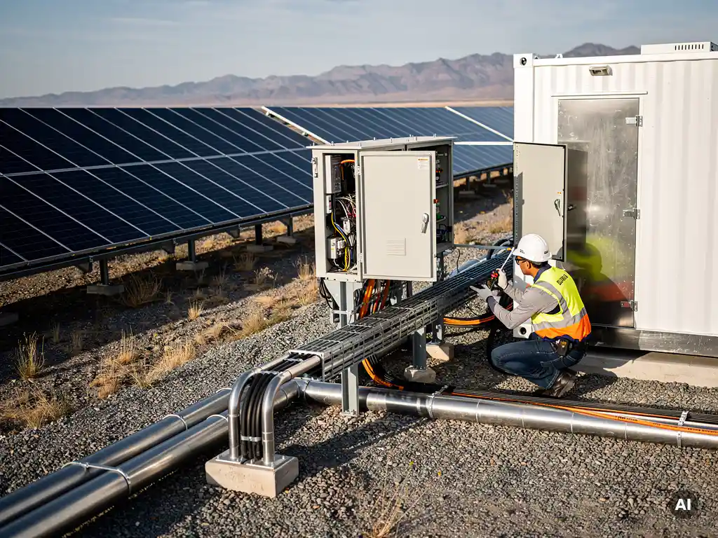
Battery storage is wired into a PV system in one of two ways: DC coupling or AC coupling. In DC coupling, the battery connects between the solar array and the inverter, storing energy before it is converted to AC. In AC coupling, the battery connects on the AC side of the system, using a separate bidirectional inverter to charge and discharge. The right approach depends on your system architecture, inverter selection, and project scale. This article walks through both methods, the components involved, how battery storage appears on a single-line diagram, and the wiring standards that govern safe installation.
What are the two main ways to wire a battery into a solar system?
The two main ways to wire a battery into a solar system are DC coupling and AC coupling. In DC coupling, the battery is connected on the DC side of the system, between the solar array and the inverter. In AC coupling, the battery connects on the AC side, after the main inverter, using its own dedicated bidirectional inverter to manage charge and discharge cycles.
Both approaches achieve the same fundamental goal, storing excess solar energy for use when generation is low or demand is high, but they do so through different electrical architectures. DC coupling tends to be more efficient because energy is converted from DC to AC only once. AC coupling is more flexible and easier to retrofit onto existing PV installations because it does not require changes to the existing inverter or DC wiring.
Choosing between the two is not simply a matter of preference. It depends on whether the system is new or existing, the inverter technology in use, the scale of the project, and how the battery will be dispatched. Understanding both topologies is essential for any engineer sizing and designing a solar-plus-storage system.
How does DC-coupled battery storage work in a PV system?
In a DC-coupled battery storage system, the battery bank connects directly to the DC bus, typically through a dedicated charge controller or a hybrid inverter that manages both the solar input and the battery simultaneously. Energy from the solar array flows into the battery in its native DC form, and the single hybrid inverter then converts DC to AC for loads or grid export. This means the energy is only converted once, making DC coupling the more efficient of the two topologies.
The most common implementation in commercial and utility-scale projects uses a hybrid inverter, sometimes called a storage-ready or all-in-one inverter, that integrates MPPT inputs for the PV array and a separate DC port for the battery. The inverter manages the energy flow intelligently: it can charge the battery from the array, discharge the battery to support loads, and export to the grid, all through a single conversion stage.
An alternative DC-coupled approach uses a separate DC-DC charge controller (often a bidirectional DC converter) placed between the array and the battery, with a standard string inverter handling the AC conversion. This configuration is less common in large-scale commercial projects but appears in some utility-scale designs where the battery chemistry or voltage range requires dedicated charge management.
The key advantage of DC coupling is round-trip efficiency. Because there is no intermediate AC conversion step during charging, losses are lower compared to AC coupling. The trade-off is that DC-coupled systems are generally designed from the ground up. Retrofitting a DC-coupled battery into an existing PV system usually requires replacing the inverter, which adds cost and complexity.
How does AC-coupled battery storage differ from DC coupling?
AC-coupled battery storage differs from DC coupling in that the battery connects on the AC side of the system, after the main solar inverter. The battery has its own dedicated bidirectional inverter (sometimes called a battery inverter or storage inverter) that converts AC from the grid or the solar inverter into DC for charging and converts DC back to AC when discharging. This means energy undergoes two conversion steps during charging, which introduces slightly higher losses than DC coupling.
Despite the efficiency trade-off, AC coupling is widely used, particularly for retrofitting battery storage onto existing solar installations. Because the battery system is electrically independent of the PV inverter, there is no need to replace or modify existing equipment. An AC-coupled battery can be added to virtually any grid-tied PV system regardless of the inverter brand or age.
In terms of system design, AC coupling also offers greater flexibility at scale. Large commercial and utility projects sometimes use AC-coupled battery systems because the battery inverter can be sized independently of the PV inverter, allowing engineers to optimize each component separately. This is particularly useful in projects where the battery is intended for grid services such as frequency response or peak shaving, rather than purely self-consumption.
The practical distinction for engineers comes down to this: DC coupling is the preferred choice for new-build systems where efficiency is the priority, while AC coupling is the practical solution for retrofits and for projects where independent battery dispatch control is required.
What electrical components are required to wire in a battery system?
Wiring a battery storage system into a PV installation requires several key electrical components beyond the battery cells themselves. The exact configuration varies between DC-coupled and AC-coupled designs, but the core components are consistent across most commercial and utility-scale projects.
- Battery management system (BMS): Monitors cell voltage, temperature, and state of charge. The BMS protects the battery from overcharge, deep discharge, and thermal events, and communicates with the inverter or energy management system.
- Hybrid or bidirectional inverter: In DC-coupled systems, the hybrid inverter manages both PV input and battery charge/discharge. In AC-coupled systems, a dedicated bidirectional battery inverter handles the AC-to-DC and DC-to-AC conversion for the battery independently.
- DC disconnect and fusing: Overcurrent protection and isolation devices on the DC side of the battery are mandatory. These include fuses or circuit breakers rated for the battery’s maximum discharge current, plus a manual disconnect for maintenance and emergency isolation.
- AC disconnect and protection: On the AC side, the battery inverter requires its own AC breaker and, in grid-tied systems, anti-islanding protection to prevent the battery from energizing the grid during an outage.
- Energy management system (EMS) or controller: Coordinates the dispatch of the battery relative to solar generation, load demand, and grid conditions. In larger commercial systems, the EMS may be a standalone controller that communicates with the inverter via Modbus or CAN bus.
- DC cabling and busbars: Appropriately sized DC cables rated for the battery voltage and current, with the correct insulation class and short-circuit protection.
- Metering: Revenue-grade or sub-metering equipment to measure battery charge and discharge for performance monitoring, billing, or grid compliance.
For utility-scale projects, additional components such as battery enclosures with integrated thermal management, fire suppression systems, and communication gateways are typically required. The component list grows with system size and the complexity of the grid interconnection agreement.
Where does the battery sit in a single-line diagram for a solar+storage system?
In a single-line diagram (SLD) for a solar-plus-storage system, the battery’s position depends on the coupling topology. In a DC-coupled system, the battery appears on the DC bus between the PV array combiners and the hybrid inverter, connected in parallel with the PV DC input at the inverter’s battery terminals. In an AC-coupled system, the battery and its bidirectional inverter appear on the AC bus, typically connected at the same point as the loads and the main PV inverter output, before the grid connection point.
On a well-drawn SLD, the battery system is represented as a distinct branch with its own protection devices clearly shown. For DC coupling, this means the battery string, BMS, DC fusing, and DC disconnect are shown between the battery terminals and the hybrid inverter’s DC input. For AC coupling, the bidirectional battery inverter, its AC breaker, and any metering are shown as a separate branch on the AC distribution board or main AC busbar.
The SLD must also clearly show the interconnection between the battery system and the grid connection point, including any transfer switches if the system is designed for backup or islanding operation. Anti-islanding protection, where required, is shown as part of the battery inverter’s AC output circuit.
For engineers working in AutoCAD or BricsCAD, tools like Virto Solar’s design platform can automate the generation of single-line diagrams for PV systems, reducing the manual drafting time that typically comes with every design revision. When battery storage is added to a project, the SLD must be updated to reflect the new protection coordination and metering requirements, something that manual workflows make time-consuming and error-prone.
What wiring standards and safety rules apply to solar battery installations?
Solar battery installations are governed by a combination of electrical wiring standards, product safety certifications, and grid interconnection requirements. The specific standards that apply depend on the country and jurisdiction, but several frameworks are widely referenced across commercial and utility-scale projects internationally.
Key international and regional standards
In Europe, battery storage systems connected to PV installations must comply with IEC 62619 (safety requirements for secondary lithium cells and batteries for use in industrial applications) and IEC 62477 (safety requirements for power electronic converter systems). Grid connection requirements are governed by national grid codes, with EN 50549 covering requirements for generating plants connected to low- and medium-voltage distribution networks across EU member states.
In the United States, the primary standard is NFPA 70 (National Electrical Code), with Article 706 specifically covering energy storage systems. UL 9540 is the product safety standard for energy storage systems, and UL 9540A governs fire testing of battery systems. Grid interconnection follows IEEE 1547, which sets requirements for distributed energy resources connecting to the grid.
Core safety rules for battery wiring
Regardless of jurisdiction, several safety principles apply universally to battery storage wiring in PV systems:
- Overcurrent protection: Every battery circuit must be protected against short-circuit and overcurrent conditions with appropriately rated fuses or circuit breakers, sized to the battery’s maximum discharge current and cable ampacity.
- Disconnection means: A readily accessible manual disconnect must be provided on the DC side of the battery, allowing safe isolation for maintenance, emergency response, and commissioning.
- Anti-islanding: Grid-tied battery inverters must include anti-islanding protection to prevent the battery from energizing the grid during a utility outage, protecting utility workers from unexpected live conductors.
- Cable sizing and routing: DC battery cables must be sized for both continuous current and short-circuit conditions, with appropriate voltage ratings for the battery system voltage. Cables should be routed to minimize fault risk and clearly labeled.
- Thermal management and ventilation: Battery enclosures must meet the thermal management requirements specified by the battery manufacturer and relevant standards, particularly for lithium-ion chemistries where thermal runaway is a recognized hazard.
- Labeling and documentation: Battery systems require clear labeling at all disconnects, inverters, and enclosures, along with updated as-built documentation including the revised SLD.
Staying current with applicable standards is an ongoing responsibility for PV engineers, as grid codes and product safety requirements continue to evolve alongside battery technology. If you are designing a solar-plus-storage project and want to ensure your electrical design meets current requirements, reaching out to our team is a good starting point for understanding how the right software tools can support accurate, compliant engineering documentation from the outset.
Frequently Asked Questions
Can I add DC-coupled battery storage to an existing solar installation without replacing my inverter?
In most cases, retrofitting DC-coupled storage onto an existing system requires replacing the current inverter with a hybrid inverter that has a dedicated battery DC port, which adds significant cost and complexity. If you want to avoid that, AC coupling is the more practical retrofit path since it leaves the existing PV inverter untouched and simply adds a bidirectional battery inverter on the AC side. The only scenario where DC coupling can be retrofitted without a full inverter swap is if your existing inverter was already designed as a storage-ready or hybrid unit with an unused battery input.
How do I size the battery inverter for an AC-coupled system?
The battery inverter in an AC-coupled system should be sized based on the peak power you need to charge or discharge, not the total battery capacity. For self-consumption applications, a common rule of thumb is to match the battery inverter’s continuous power rating to the expected peak load the battery will need to support during a grid outage or peak demand period. For grid services such as frequency response or peak shaving, the inverter sizing is driven by the contracted power obligation rather than the battery energy capacity, so always confirm the dispatch requirements with the grid operator or off-taker before finalizing the design.
What is the typical round-trip efficiency difference between DC-coupled and AC-coupled systems?
DC-coupled systems typically achieve round-trip efficiencies in the range of 92–96%, while AC-coupled systems generally fall between 87–92%, depending on the inverter efficiency curves and the battery chemistry used. The gap exists because AC coupling introduces an additional conversion step during charging, where AC from the grid or PV inverter is converted to DC by the battery inverter before entering the battery. For projects where self-consumption or energy arbitrage is the primary revenue driver, this efficiency difference can meaningfully affect the financial model over a 10–15 year project life.
What is the most common mistake engineers make when drawing a battery storage single-line diagram?
One of the most frequent errors is omitting or incorrectly placing the DC disconnect and overcurrent protection devices on the battery branch, which is both a code violation and a serious safety gap. Another common mistake is failing to show the anti-islanding protection as a distinct element on the AC output of the battery inverter, particularly in AC-coupled designs where the battery inverter is a separate device from the PV inverter. A well-drawn SLD should clearly trace every protection device, metering point, and communication link so that the diagram can stand alone as a complete engineering document for permitting and commissioning.
Does adding battery storage change the grid interconnection agreement for an existing solar project?
Yes, in most jurisdictions adding battery storage to an existing grid-tied solar system triggers a review or amendment of the existing interconnection agreement, even if the export capacity does not change. Grid operators need to assess how the battery’s charge and discharge behavior affects power quality, fault current contribution, and anti-islanding compliance under standards such as IEEE 1547 in the US or EN 50549 in Europe. It is strongly advisable to notify your grid operator before installation begins rather than after, as retroactive compliance issues can delay commissioning and, in some cases, require costly design changes.
How does the battery management system (BMS) communicate with the inverter, and why does it matter for system design?
The BMS typically communicates with the inverter using protocols such as CAN bus, Modbus RTU, or Modbus TCP/IP, depending on the manufacturer’s implementation. This communication link is critical because it allows the inverter to receive real-time data on state of charge, cell temperature, and allowable charge/discharge limits, enabling safe and optimized battery dispatch. When selecting a hybrid or battery inverter, engineers must verify that the BMS communication protocol is compatible with the chosen inverter brand, as mismatched protocols can prevent the system from operating correctly and may void product warranties.
Are there specific fire safety requirements I need to account for when installing lithium-ion battery storage in a commercial building?
Yes, lithium-ion battery systems in commercial buildings are subject to fire safety requirements that go beyond standard electrical codes, including compliance with UL 9540A fire testing results and local fire codes such as NFPA 855, which sets installation requirements for stationary energy storage systems in the US. Key considerations include minimum separation distances between battery enclosures, ventilation or active thermal management to prevent heat accumulation, and in some cases, integrated fire suppression systems within the battery enclosure. Always coordinate with the authority having jurisdiction (AHJ) early in the design process, as fire marshal approvals for large lithium-ion installations can add significant lead time to a project schedule.
Related Articles
This content was generated with the help of AI — it may contain mistakes
Source link