

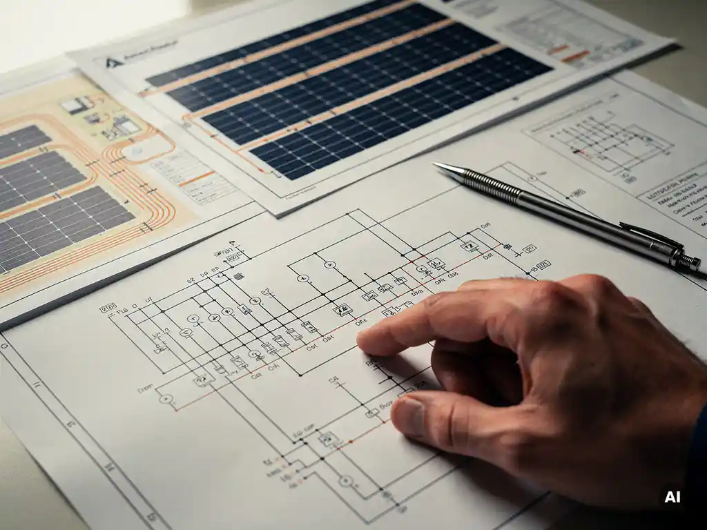
Solar wiring diagrams use standardized electrical symbols to represent every component in a photovoltaic system, including PV modules, inverters, combiners, protection devices, and conductors. These symbols follow internationally recognized standards such as IEC 60617 and IEEE standards, ensuring that any qualified engineer can read and interpret a diagram regardless of who created it. This article breaks down the most common symbols used in solar wiring diagrams and answers the questions engineers ask most often about them.
What do the symbols in a solar wiring diagram represent?
Symbols in a solar wiring diagram are standardized graphical shorthand for every electrical component and connection in a PV system. Rather than writing out “photovoltaic module” or “DC disconnect switch” in full, engineers use agreed-upon icons that communicate the same information instantly, reducing ambiguity and making designs readable across teams, contractors, and inspection authorities.
Each symbol carries specific meaning. A symbol’s shape identifies the component type, while annotations alongside it, such as voltage ratings, current values, or model references, add the project-specific detail. Lines connecting symbols represent conductors, with line weight or style often indicating whether the conductor is DC or AC, single-phase or three-phase.
In a complete solar wiring diagram, you will typically encounter symbols for:
- PV modules and arrays
- String combiners and junction boxes
- Inverters and charge controllers
- DC and AC disconnect switches
- Overcurrent protection devices (fuses and circuit breakers)
- Surge protection devices (SPDs)
- Meters and monitoring equipment
- Grounding and earthing connections
- The utility grid connection point
Understanding what each symbol represents is the foundation of reading or producing any solar electrical drawing accurately.
What symbols are used for PV modules and arrays?
A single PV module is typically represented by a diode-like symbol inside a rectangle, or by a simplified cell symbol showing a positive and negative terminal with a small arrow indicating light energy input. When multiple modules are wired in series to form a string, the symbols are shown connected end-to-end. An array of multiple strings is often represented as a grouped block with annotation indicating the number of modules per string and the number of strings.
In more detailed engineering drawings, each string may be shown individually with its own conductor run back to the combiner box or inverter input. In simplified or single-line diagrams, the entire array is often condensed into a single block labeled with total capacity in kilowatts-peak (kWp) and the string configuration, for example “10 strings x 20 modules.”
Bypass diodes, which are built into module junction boxes to reduce the impact of shading, are sometimes shown explicitly within the module symbol as small diode icons. String diodes, where used, appear on the conductor line between the string and the combiner.
How are inverters and charge controllers shown in a solar diagram?
Inverters are represented by a rectangle or box symbol containing a tilde (~) or sine wave on the AC output side and a straight line on the DC input side, visually communicating the DC-to-AC conversion function. For three-phase inverters, three output lines are shown leaving the symbol. Central inverters, string inverters, and microinverters may each be drawn differently depending on how they connect to the array and the grid.
Charge controllers, used primarily in off-grid and hybrid systems, are shown as a rectangular block positioned between the PV array and the battery bank. The symbol often includes directional arrows or labels indicating the charge regulation function. Maximum power point tracking (MPPT) controllers may be labeled explicitly to distinguish them from simpler pulse-width modulation (PWM) types.
In utility-scale and commercial diagrams, the inverter symbol is typically accompanied by key electrical parameters: input voltage range, maximum DC input current, AC output voltage, and power rating. These annotations are as important as the symbol itself for engineering review and permitting purposes.
What symbols represent protection and safety devices?
Protection and safety devices have their own distinct symbols in solar wiring diagrams, and correctly identifying them is critical for both design review and on-site safety. The most common protection symbols include:
- Fuse: Shown as a small rectangle or an oval with a line through it, placed in series on a conductor to indicate overcurrent protection for that circuit.
- Circuit breaker: Represented by a switch symbol with a curved line or a specific IEC/IEEE breaker icon, indicating a resettable overcurrent device.
- Surge protection device (SPD): Shown as a box or arrester symbol connected between the conductor and earth, indicating transient overvoltage protection.
- DC disconnect switch: A simple switch symbol on the DC conductor run, indicating a manual isolation point between the array and the inverter.
- AC disconnect switch: The same switch symbol placed on the AC side, between the inverter and the grid connection.
- Ground-fault protection device (GFPD): Often shown as a specialized relay or detector symbol, particularly in US-market diagrams following NEC requirements.
- Earthing/grounding connection: Shown as a series of horizontal lines decreasing in length, indicating a connection to earth potential.
In commercial and utility-scale designs, protection devices are not optional annotations. They are mandatory elements that must appear in the correct location on the diagram to satisfy grid connection requirements and local electrical codes.
What’s the difference between a solar wiring diagram and a single-line diagram?
A solar wiring diagram shows every individual conductor, connection, and component in full detail, while a single-line diagram (SLD) represents the entire electrical system using a single line to symbolize all conductors in a circuit, regardless of the actual number of wires. The SLD is a simplified, high-level overview; the wiring diagram is the detailed, construction-level document.
In practice, both documents serve different purposes and audiences. A single-line diagram is typically used for permitting, utility interconnection applications, and high-level design reviews. It communicates the system architecture, protection scheme, and power flow without the visual complexity of every individual conductor. An inspector or utility engineer can quickly verify that the system meets code requirements from an SLD.
A detailed wiring diagram, by contrast, is used by installation crews and commissioning engineers. It shows exactly how each component connects, which terminals to use, what conductor sizes are specified, and where every protection device sits in the circuit. Both documents use the same core symbol library, but the level of detail and the intended reader are different.
For large commercial and utility-scale projects, producing accurate SLDs manually in AutoCAD is one of the most time-consuming steps in the engineering workflow. Tools like Virto Solar’s Virto.CAD automate SLD generation directly from the design data, eliminating the need to redraw diagrams every time a design parameter changes.
Which standards define solar electrical diagram symbols?
Solar electrical diagram symbols are primarily defined by two international standards bodies: the International Electrotechnical Commission (IEC) and the Institute of Electrical and Electronics Engineers (IEEE). The applicable standard depends on the project’s geographic market and the engineering conventions used by the design team.
IEC 60617
IEC 60617 is the dominant standard for graphical symbols used in electrical diagrams across Europe, Asia, and most international markets. It provides a comprehensive library of symbols covering everything from basic conductors and switches to complex protection relays and power conversion equipment. Most solar projects outside North America reference IEC 60617 as the basis for their diagram symbols.
IEEE and NEC standards
In the United States and Canada, IEEE standards and the National Electrical Code (NEC) shape the symbols and conventions used in solar electrical drawings. While many symbols overlap with IEC conventions, there are notable differences, particularly in how grounding, overcurrent protection, and disconnecting means are represented. Engineers working on projects for US utilities or permitting authorities need to be familiar with these distinctions.
Beyond the symbol standards themselves, projects may also reference IEC 62446, which specifies the documentation requirements for grid-connected PV systems, including what diagrams must be produced and what information they must contain. Following these standards is not just good practice. It is often a contractual or regulatory requirement for project approval and grid connection.
If you are working on commercial or utility-scale PV projects and want to streamline how your team produces compliant electrical drawings, get in touch with us to see how our software handles symbol-accurate, standards-compliant diagram generation automatically.
Frequently Asked Questions
Can I use IEC symbols on a project that will be submitted to a US permitting authority?
It depends on the authority having jurisdiction (AHJ). Some US permitting authorities and utilities accept IEC-based symbols, especially on projects with international engineering teams, but many expect IEEE and NEC-aligned conventions for grounding, overcurrent protection, and disconnecting means. The safest approach is to confirm the AHJ’s requirements before finalizing your drawings, and if necessary, produce a version of the diagram that maps to the expected US conventions. Mixing symbol sets without clear notation in the drawing legend is a common reason for permit rejections.
What should a drawing legend or symbol key include in a solar wiring diagram?
A drawing legend should list every symbol used in the diagram alongside its written description, the standard it references (e.g., IEC 60617 or IEEE), and any project-specific variations. It should also clarify line style conventions, such as which line weight represents DC conductors versus AC conductors, and whether dashed lines indicate future expansion or conduit runs. A well-constructed legend makes the diagram self-contained, meaning any qualified engineer or inspector can interpret it without needing to reference external documents or ask the design team for clarification.
How do I represent a battery storage system in a solar wiring diagram?
A battery bank is typically represented by a series of alternating long and short parallel lines, which is the standard electrochemical cell symbol, grouped together to indicate multiple cells or modules. The battery management system (BMS) is shown as a separate rectangular block connected between the battery and the rest of the circuit. For AC-coupled storage systems, the storage inverter or bidirectional inverter has its own symbol distinct from the PV inverter, and the diagram should clearly show the power flow direction in both charge and discharge modes. Annotations should include the battery’s nominal voltage, usable capacity in kWh, and chemistry type where relevant.
What are the most common mistakes engineers make when drawing solar wiring diagrams?
The most frequent mistakes include omitting mandatory protection devices such as DC GFPDs or SPDs from the diagram, using inconsistent symbols that mix IEC and IEEE conventions without a clear legend, and failing to annotate conductor sizes, voltage ratings, and current values alongside the symbols. Another common error is not updating the wiring diagram when design parameters change, leading to a mismatch between the diagram and the actual bill of materials or system configuration. For teams managing multiple projects simultaneously, this version-control problem is one of the strongest arguments for using software that generates diagrams directly from live design data rather than maintaining them manually.
Do microinverter systems require a different wiring diagram approach than string inverter systems?
Yes, microinverter systems require a notably different diagram structure because the DC-to-AC conversion happens at each module rather than at a central or string inverter. In a microinverter wiring diagram, each module-microinverter pair is shown as a combined unit, and the conductors leaving the array are AC rather than DC, which must be clearly indicated in the diagram. The combiner or trunk cable aggregating the AC output of multiple microinverters is shown differently from a DC string combiner, and there is no DC disconnect between the array and an inverter in the traditional sense. Engineers new to microinverter diagrams should pay particular attention to how AC branch circuits, the AC combiner, and the interconnection point are represented to avoid confusion during inspection.
How detailed does a wiring diagram need to be for a utility interconnection application?
Most utilities require a single-line diagram (SLD) rather than a fully detailed wiring diagram for the interconnection application itself, but the SLD must include specific elements: the point of common coupling (PCC), all protection and disconnecting devices, the inverter specifications, metering location, and the grounding scheme. Some utilities also require a three-line diagram for larger three-phase systems to show phase relationships and protection coordination. It is essential to review the utility’s specific interconnection technical requirements before submitting, as missing a required element, such as an anti-islanding protection notation, is a common cause of application delays.
Is there software that can automatically generate standards-compliant solar wiring diagrams and SLDs?
Yes, specialized PV engineering software can generate single-line diagrams and wiring diagrams directly from system design data, automatically applying the correct symbols, annotations, and layout conventions based on the target market standard (IEC or NEC). This eliminates the manual redrawing effort in AutoCAD every time a design parameter changes and significantly reduces the risk of symbol errors or outdated diagrams. Virto Solar’s Virto.CAD is one such tool, purpose-built for commercial and utility-scale PV projects, and it produces permit- and grid-connection-ready electrical drawings as a direct output of the design workflow.
Related Articles
This content was generated with the help of AI — it may contain mistakes
Source link