

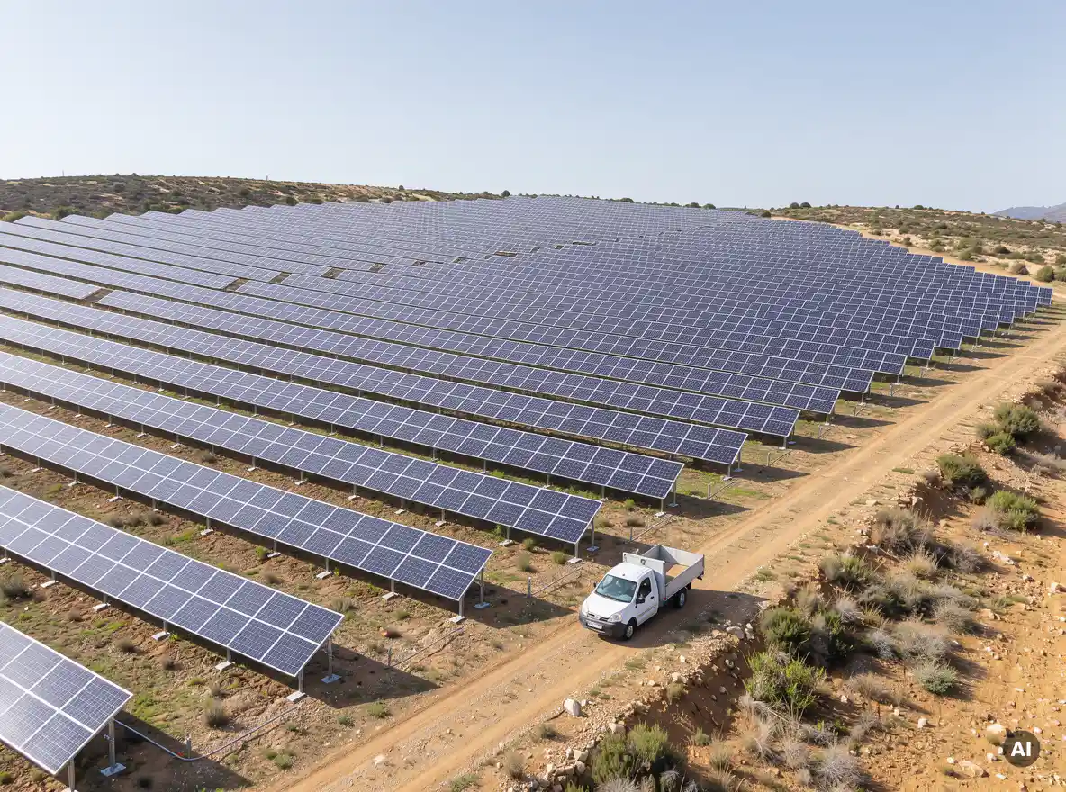
Because modules in a string share current, even small shaded areas can cause outsized losses, which makes the layout one of the cheapest places to protect yield. Below, we answer the questions engineers ask most about spacing, orientation, string arrangement, and modeling.
How does panel placement actually create shading losses?
Panel placement creates shading losses when modules sit where obstacles, neighboring rows, or other modules cast shadows on them. Because cells in a module are wired in series, one shaded cell limits the current of the whole substring, so the loss is far larger than the shaded area alone.
Shading comes from several sources, and a good layout accounts for each of them:
Inter-row shading: the back of one row shadows the front of the next, especially at low sun angles in winter and during early morning and late afternoon.
Near-object shading: parapets, HVAC units, skylights, roof edges, and rooftop cabling that sit close to the array.
Far-object shading: trees, buildings, and terrain on the horizon that block the sun at certain times of day.
Self-shading: tilted modules or tables casting shade on adjacent modules within the same field.
Bypass diodes limit the damage by letting current skip a shaded substring, but each diode activation removes a chunk of module output. This is why the placement of each table, not just the total module count, shapes your energy yield.
How much row spacing is needed to avoid inter-row shading?
Row spacing must be large enough that the shadow from one row does not reach the next row during the hours you want to protect. Engineers commonly design around the winter solstice, using a clear window such as 9:00 to 15:00 solar time. The required distance grows with tilt angle, module height, and site latitude.
The logic is simple. A steeper tilt raises the top edge of the table, which lengthens the shadow it casts. A site farther from the equator has a lower winter sun, which lengthens it again. To find the minimum pitch, you calculate the shadow length from the lowest sun elevation in your design window and add that to the table’s footprint.
Why spacing is always a trade-off
Wider spacing cuts shading but reduces the capacity you can fit on the same land or roof. On a rooftop with fixed area, you may accept a small amount of shading to gain extra modules. On a ground-mount site, land cost and DC/AC ratio targets shape the answer. The goal is the best energy per available area, not zero shading at any price.
Flat roofs and low tilt
On flat commercial roofs, low-tilt east-west layouts allow much tighter pitch because the modules sit lower and shade each other less. They often yield more per square meter even if the yield per kWp is slightly lower. Comparing options early saves a lot of rework later.
Does module orientation change how shading affects output?
Yes. Module orientation changes shading impact because it controls how shadows cross the cell and substring layout. In portrait, a low shadow from a row in front often covers a whole substring at once. In landscape, the same shadow may cover only one substring, so the module keeps more of its output.
This depends on how the bypass diodes divide the module. In many standard modules, substrings run along the long side, so a shadow rising from the bottom edge in portrait orientation can switch off one substring, while in landscape it can affect several cells across all of them. Always check the module datasheet and wiring diagram before choosing orientation.
Other factors matter too. Half-cut cell modules split the module into upper and lower halves, which behave differently under inter-row shade than a standard three-diode design. Rooftop obstacles may also favor one orientation over another, so test both rather than assuming. The right choice depends on the shading pattern at your specific site.
How should strings be arranged to limit shading impact?
Strings should group modules that receive similar irradiance, so a shadow affects as few strings as possible. Instead of running a string across areas with different shading, keep each string within one table, one row, or one uniformly lit zone, and match string size to the inverter’s MPPT voltage window.
Practical rules for string layout include:
Keep shaded and unshaded modules on separate strings or separate MPPT inputs.
Run strings along the direction of the shadow edge so the whole string is shaded at the same time, not module by module.
Avoid mixing orientations or tilts within one string.
Check that the longest and shortest strings stay within the inverter’s voltage limits at both temperature extremes.
Consider module-level power electronics only for areas where shading cannot be designed out.
The reason is mismatch. When strings share an MPPT input, the inverter tracks one operating point for all of them, so a poorly lit string pulls down its better-lit neighbors. Smart string planning is often the difference between a shading loss of a few percent and a much larger one.
What is the best way to model shading losses before construction?
The best way to model shading losses is to build a 3D scene of the site with all obstacles, run a time-step shading simulation across the full year, and feed the result into an energy yield model. This shows which modules lose output, when, and how much that costs in annual kWh.
A reliable workflow looks like this:
Capture accurate site geometry, including building heights, parapets, trees, and terrain.
Place the modules and tables with the intended tilt, pitch, and orientation.
Run a shading analysis that accounts for both direct and diffuse light and for the electrical effect on strings, not only the geometric shaded area.
Export the loss factors to your yield simulation and compare layout variants.
Doing this by hand in spreadsheets works for small jobs but gets slow and error-prone because every layout change forces you to redo the calculations. This is where we built Virto.CAD to help. It runs shading analysis inside AutoCAD and BricsCAD, so you can adjust the layout and see the effect without leaving your drawing, and it stays compatible with PVsyst for the final yield study.
How can layout shading losses be verified and reduced further?
Verify layout shading losses by comparing your simulation against the shading diagram, checking monthly and hourly loss patterns, and testing alternative layouts. Then reduce losses by adjusting pitch, tilt, orientation, or string grouping, or by removing the few modules that cause the biggest losses.
Useful checks and improvements include:
Review the loss breakdown: separate near-shading, far-shading, and electrical mismatch so you fix the right cause.
Remove problem modules: deleting a handful of heavily shaded modules can raise yield for the rest of the string.
Test pitch variants: small spacing changes often recover more energy than expected.
Reassign strings: regrouping modules by irradiance can cut mismatch without moving any hardware.
Validate on site: after commissioning, compare measured production against the model to confirm your assumptions.
Treat the layout as something you refine in several passes, not a one-time decision. Automation helps here because it lets you test more variants in less time. If you want to see how this works on your own projects in 2026, get in touch with our team and we will gladly walk you through it.
Frequently Asked Questions
Where should I start when designing a layout to minimize shading losses on an existing rooftop?
Start with an accurate site survey that captures roof dimensions, parapet heights, and the position and height of obstacles like HVAC units, vents, and nearby trees or buildings. Place a first-pass layout with a reasonable tilt and pitch, then run a shading simulation to identify the worst-affected modules. From there, iterate by adjusting spacing, moving or removing problem modules, and regrouping strings.
What if I can’t achieve the ideal row spacing because roof or land area is limited?
Accept a small, controlled amount of shading rather than sacrificing too much capacity, but quantify the trade-off with a yield simulation. Options include reducing tilt, switching to a low-tilt east-west layout, or shortening the shading window you design for (for example 10:00 to 14:00 instead of 9:00 to 15:00). Compare annual kWh per square meter across variants to pick the best balance.
When is it worth using optimizers or microinverters instead of redesigning the layout?
Module-level power electronics make sense when shading cannot be designed out, such as unavoidable chimneys, irregular rooflines, or obstacles that cast changing shadows across many modules. For unshaded areas, a well-planned string layout is usually more cost-effective. A good approach is to use module-level electronics only on the specific shaded sections rather than on the entire array.
How do I decide between portrait and landscape orientation for a specific project?
Check the module’s datasheet to see how bypass diodes and substrings are arranged, then simulate both orientations against your site’s real shading pattern. Inter-row shadows rising from the bottom edge often behave very differently in each orientation, and half-cut modules change the result again. Let the simulated annual loss decide rather than a general rule.
What are the most common layout mistakes that increase shading losses?
Frequent mistakes include designing spacing only for the summer sun, mixing shaded and unshaded modules on the same string or MPPT input, ignoring small near-objects like cable trays and parapets, and mixing tilts or orientations within one string. Another common error is relying on geometric shaded area alone instead of modeling the electrical effect on strings.
How can I check that my shading model matches real-world performance after the system is built?
Compare measured production and inverter data against your simulated output, looking at monthly and hourly patterns, especially around the early morning, late afternoon, and winter hours when shading is strongest. If the actual output falls short of the model, review whether obstacle heights, as-built tilt, and string assignments match the design. Feed those findings back into future designs to improve accuracy.
Is it better to remove a few heavily shaded modules or keep them in the array?
Often removing a handful of heavily shaded modules improves overall yield, because they drag down the current of every other module in the same string. Run a before-and-after simulation to confirm the gain against the lost capacity. If the modules sit on a separate MPPT input or string, keeping them may still be worthwhile.
Related Articles
This content was generated with the help of AI — it may contain mistakes
Source link