

How does row spacing affect shading losses?
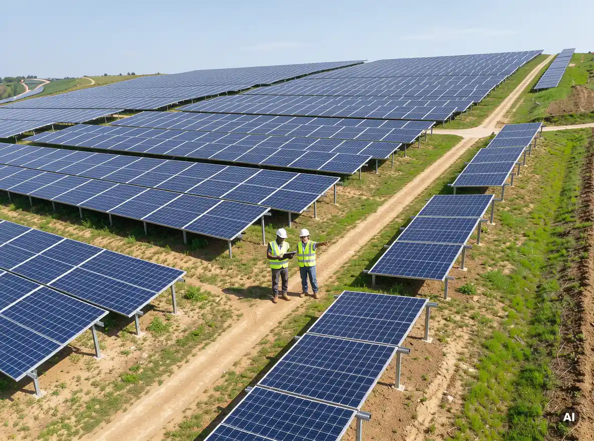
Row spacing sets how much one row of modules shades the next, especially in winter when the sun sits low. Wider spacing cuts inter-row shading but uses more land and cable. Tighter spacing improves land use but raises shading losses, so the right pitch is a trade-off.
The key driver is the design sun position, usually the winter solstice during a chosen time window, and the shadow length cast by the row at your tilt. A steeper tilt creates a longer shadow, which means a larger pitch is needed to keep the same shade-free window. Many engineers define a no-shade period (for example, 9:00 to 15:00 solar time on the shortest day) and work backward to a minimum pitch.
Pay attention to the ground coverage ratio (GCR) as well. A higher GCR packs more kWp into the same area, but electrical shading on modules and strings can cost more than the extra capacity gains. Remember that partial shading hits a string harder than the shaded area alone suggests, because shaded cells can limit the current of an entire series connection. Running a proper shading analysis at the layout stage, instead of after drawings are finished, saves expensive rework.
How do tilt and orientation change layout decisions?
Tilt and orientation determine how much irradiance the modules capture and how large the layout must be. Tilt influences annual yield and row pitch, while orientation (azimuth) shifts when energy is produced. Together they decide the module count per area, the inter-row distance, and the shape of the production curve.
In the northern hemisphere, south-facing arrays at a latitude-based tilt usually maximize annual yield for ground-mount systems. But maximum yield per module is not always the goal. A lower tilt shortens shadows, allowing tighter rows and more capacity per hectare. East-west layouts trade some peak yield for higher density, a flatter daily production curve, and often better use of flat rooftops with limited ballast capacity.
For rooftops, the roof pitch and azimuth often dictate the answer for you, so the question becomes how to place modules efficiently within those limits. For ground-mount sites, terrain slope can push the optimal azimuth away from true south. In both cases, comparing a few tilt and orientation options with yield simulations beats relying on rules of thumb.
Which site constraints should be mapped before placing modules?
Map every physical, regulatory, and structural limit before placing a single module. These include property boundaries, setbacks, access roads, fire pathways, obstructions, terrain slope, soil conditions, and distances to the grid connection point. Placing modules first and discovering constraints later leads to redesign.
Rooftop projects
On rooftops, start with the usable area. Mark parapets, skylights, HVAC units, vents, drainage, and walkways. Account for fire-safety setbacks and maintenance access, and check roof load limits, because ballasted systems add weight. Nearby objects such as chimneys or higher building sections also cast shadows that should be modeled.
Ground-mount projects
On ground-mount sites, map the boundary and setbacks, slope and aspect, drainage or flood zones, existing vegetation, and soil data that affects foundation type. Add cable routes, trenches, and inverter or transformer station locations early, since long cable runs add both cost and voltage drop. Terrain with steep or irregular slopes may require adjusted row pitches or segmented layouts.
How should strings and inverters be matched to the layout?
Strings and inverters should be matched so that each string stays within the inverter’s voltage and current limits across the site’s temperature range, while the DC/AC ratio fits the project economics. The physical layout should follow the electrical design, keeping strings compact, uniformly oriented, and similarly shaded.
Start with the module and inverter datasheets. The maximum string length is limited by the open-circuit voltage at the coldest expected temperature, and the minimum length by the MPPT voltage window at high temperature. Then check the current limits of each MPPT input and the overall DC/AC ratio. Many designers accept some clipping in exchange for a lower inverter cost per kWp, but the right ratio depends on the local irradiance profile and tariff structure.
Layout matters here, too. Avoid mixing modules with different tilts, orientations, or shading conditions on the same string or MPPT, because the weakest module sets the pace. Group strings by table or row, and place inverters or combiner boxes close to their string clusters to keep DC cable lengths and losses down. When a module specification changes, a connected workflow means string and cable calculations update with it instead of being redone by hand.
How do you balance energy yield against cost in a layout?
Balance yield against cost by looking at the levelized cost of energy (LCOE) or return on investment, not just the kWh produced. The layout with the highest yield per module is rarely the cheapest per kWh once land, structure, cabling, and installation effort are included.
Several levers pull in different directions:
- Row pitch: wider spacing reduces shading losses but increases land and cable costs.
- Tilt: a higher tilt can lift yield but needs a larger pitch and stronger structures.
- DC/AC ratio: a higher ratio lowers inverter cost per kWp but introduces clipping.
- Cable routing: shorter runs reduce copper cost and resistive losses, but may constrain module placement.
- Mounting system: the choice of racking affects installation time, material cost, and allowable layouts.
The practical approach is to compare several layout variants side by side, each with a yield simulation and a bill of materials, then pick the one with the best overall economics. This is only realistic when generating variants is fast. If every option takes days of manual redrawing, most teams settle for the first workable design.
Can layout design be automated without leaving CAD?
Yes. Layout design can be automated inside AutoCAD or BricsCAD with a PV plugin that handles module placement, string planning, shading analysis, cable sizing, and single-line diagrams. Engineers keep their familiar drawing environment while repetitive calculations and redraws happen automatically.
That is what we built Virto.CAD to do. It automates tasks such as inverter sizing, string configuration, DC/AC wiring layouts, cable tray routing, tilt angle calculations, and bill of materials generation for rooftop, ground-mount, and carport projects. Because the design data stays connected, a change to a module or row pitch flows through to downstream calculations instead of triggering a full manual rework. In one documented project in Belgium, this approach reduced design time by 80%, saving several weeks of work.
For earlier stages, such as tenders and quick feasibility checks, our web tool Virto.MAX generates layouts and energy simulations in minutes, so you can screen options before committing engineering hours. If you want to see how this fits your current workflow, you can contact us and we will gladly talk it through.
In short, strong solar panel layout design comes from treating spacing, tilt, site limits, electrical matching, and cost as a single system. Test several variants, let the numbers decide, and automate the repetitive parts so more of your time goes into optimization.
Frequently Asked Questions
Where should I start when designing a PV layout from scratch?
Start by collecting site data: boundary or roof outline, setbacks, obstructions, terrain slope, and the grid connection point. Next, pick a module and inverter from the datasheets, define a no-shade window for the winter solstice, and calculate a preliminary row pitch for a few tilt options. Run a quick yield simulation on each variant before drawing detailed plans, so you only invest drafting time in the most promising option.
What is a good ground coverage ratio (GCR) to aim for?
There is no single ideal GCR because it depends on latitude, tilt, terrain, land cost, and tariff structure. Fixed-tilt ground-mount systems often fall somewhere between 0.3 and 0.5, while east-west layouts can go considerably higher. Test several GCR values in a shading and yield simulation and compare LCOE rather than just kWp per hectare, since the densest layout is not always the most profitable.
What if my site has uneven or sloped terrain?
Split the site into zones with similar slope and aspect, and adjust row pitch and tilt for each zone instead of using one uniform value. North-facing slopes (in the northern hemisphere) need much larger pitches to avoid shading, while south-facing slopes allow tighter rows. Use a terrain model or survey data in your shading analysis, and consider following the terrain with the racking to limit earthworks and cost.
What are the most common mistakes in solar panel layout design?
Frequent errors include placing modules before mapping setbacks and fire pathways, using rule-of-thumb row spacing without a shading analysis, and mixing different orientations or shading conditions on the same string or MPPT. Others are ignoring cold-temperature open-circuit voltage when sizing strings, and overlooking DC cable length and voltage drop. Catching these at the layout stage is far cheaper than fixing them after drawings are issued.
When does an east-west layout make more sense than a south-facing one?
East-west layouts work well when roof area or ballast capacity is limited, since low tilts allow very tight rows and more kWp per square meter. They also deliver a flatter daily production curve, which can be valuable when self-consumption or morning and evening tariffs matter. The trade-off is lower peak yield per module, so compare both options using simulated energy output and bill of materials before deciding.
How many layout variants should I compare before choosing a design?
Aim for at least three to five variants that differ in key levers such as tilt, row pitch, orientation, and DC/AC ratio. Evaluate each one on yield, shading losses, cable length, and total cost to find the best LCOE or return on investment. Automation makes this practical, since manually redrawing each option can take days and discourage thorough comparison.
How do I handle design changes late in the project, such as a different module model?
A module change affects dimensions, row pitch, string length, cable sizing, and the bill of materials, so doing it by hand risks inconsistencies. Keep the design data connected, for example by using a PV plugin in AutoCAD or BricsCAD, so updates cascade through string and cable calculations automatically. After the change, re-verify the string voltage limits at minimum temperature and the DC/AC ratio before issuing revised drawings.
Related Articles
This content was generated with the help of AI — it may contain mistakes
Source link