

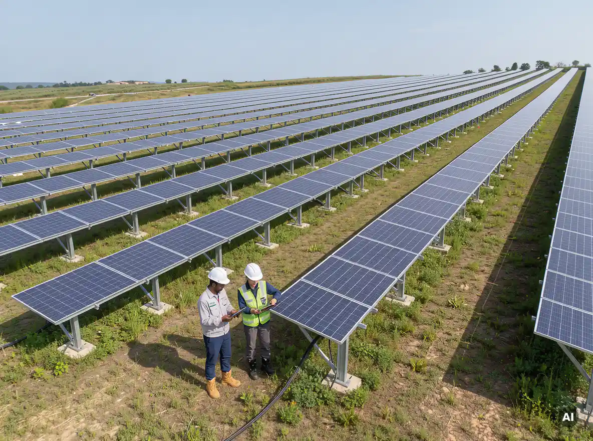
What site data is needed before starting a ground mount layout?
Before placing a single table, you need a surveyed site boundary, a topographic model, geotechnical results, and a list of constraints such as setbacks, easements, and flood zones. Without these inputs, every layout decision rests on assumptions that tend to surface as costly rework during construction.
Gather these items first:
- Site boundary and exclusion zones: property lines, setbacks, wetlands, protected areas, existing structures, and utility corridors.
- Topography: a digital terrain model (DTM) or contour data, ideally from a drone or LiDAR survey, so slope and aspect can be analyzed across the whole site.
- Geotechnical report: soil type, pile pull-out test results, and groundwater depth, which influence foundation type and table dimensions.
- Climate and shading data: irradiance, snow and wind loads, plus any horizon or nearby obstacles that cast shade.
- Equipment specifications: the module datasheet, mounting system limits, and inverter model, since table size and string length depend on them.
- Grid connection point: location and capacity of the substation or point of interconnection.
Confirm the data is current and in a consistent coordinate system. A mismatch between survey and CAD coordinates is a surprisingly common source of early errors.
How do you choose tilt, orientation, and row spacing?
Choose the tilt and orientation that maximize annual energy for your latitude, then set row spacing so that inter-row shading stays within an acceptable loss on the winter design day. In practice, these three variables are balanced against land use, because tighter rows mean more capacity on the same land but more shading.
For fixed-tilt systems in the northern hemisphere, panels typically face south, and the optimal tilt is often close to the site latitude, adjusted downward for yield-focused or land-constrained designs. East-west layouts use shallow tilts and tighter spacing, which can raise DC capacity per hectare and flatten the production curve across the day.
To set row spacing, follow this order:
- Define the design sun position, commonly solar noon on the winter solstice or a chosen morning and afternoon cutoff.
- Calculate the shadow length cast by the back edge of the table at that sun position.
- Set the pitch (row-to-row distance) so the next row stays unshaded, or accept a defined shading loss.
- Validate the result with a shading simulation or yield model such as PVsyst rather than relying on rules of thumb.
Row spacing is a trade-off, not a fixed number. Compare a few pitch values against the ground coverage ratio (GCR) and the resulting specific yield to find the best balance for your site and budget.
How do you lay out tables and strings on uneven terrain?
On uneven terrain, follow the natural slope where possible, group tables into zones with similar gradients, and let the mounting system absorb small height changes through variable pile heights. Strings should follow table rows so that cable runs stay short and each string sees consistent irradiance and shading.
Work with the terrain, not against it
Analyze slope and aspect across the site and flag areas that exceed the mounting system’s limits. North-south slope matters most for row spacing: on a south-facing slope, rows can sit closer together, while on a north-facing slope they need more room. Where grading is expensive, adapt the layout to follow contours instead of flattening the land.
Keep strings electrically and physically coherent
Group strings by table or row, and avoid mixing modules with very different shading profiles in one string, since the weakest module limits the rest. Respect the string length limits set by module voltage, inverter MPPT window, and temperature extremes. Where terrain forces shorter rows, plan partial tables and make sure string counts still divide cleanly into inverter inputs.
How should inverters, DC cabling, and access roads shape the layout?
Inverter placement, DC cable routes, and access roads should shape the layout from the start, because they determine cable losses, construction cost, and long-term maintainability. A layout that looks efficient on paper but forces long cable runs or blocks vehicle access usually costs more than it saves.
Keep these principles in mind:
- Inverter location: place string inverters or central stations near the center of their connected arrays to shorten DC runs and balance voltage drop.
- Cable routing: plan trenches and cable paths early, group cables where possible, and size them to keep DC losses within your target. Shorter, cleaner routes also reduce material and installation time.
- Access roads: provide perimeter and internal roads wide enough for construction vehicles and maintenance, with turning space and clearance around inverter stations.
- Stormwater and fencing: leave room for drainage paths, fencing, and clearance zones around equipment.
Treating these elements as constraints from day one avoids the common situation where the array is “finished” and then has to be reshuffled to fit an inverter pad or road.
What are the most common ground mount layout mistakes?
The most common ground mount layout mistakes are inadequate site data, row spacing that ignores shading, string layouts that disregard inverter limits, and cable routes added as an afterthought. Most of these errors are cheap to fix in design and expensive to fix once piles are in the ground.
Watch for these frequent issues:
- Starting the layout before geotechnical and survey data are confirmed.
- Using a single row pitch across terrain with varying slope and aspect.
- Letting strings exceed voltage limits at cold temperatures.
- Overlooking setbacks, easements, or drainage paths until late in the process.
- Placing inverters without checking cable length and voltage drop.
- Forgetting maintenance access between blocks of tables.
- Updating the layout but not the downstream calculations, so drawings, BOMs, and single-line diagrams drift out of sync.
That last point deserves attention. When a module or table changes, every dependent number has to follow. If those updates are done by hand across spreadsheets and drawings, small inconsistencies are almost guaranteed.
How can you speed up layout revisions without redoing everything?
You can speed up layout revisions by linking your layout to the calculations that depend on it, so a change to a module, tilt, or boundary updates strings, cabling, and quantities automatically. Parametric, automated workflows replace the manual rework that makes every revision feel like starting over.
A few habits help regardless of the tools you use:
- Define your design rules once (pitch, setbacks, string length, cable limits) and reuse them across revisions.
- Work in the CAD environment you already know, so drawings and data stay in one place.
- Automate repetitive steps such as table placement, string planning, and BOM generation.
- Keep a clear revision history so you can compare options and roll back if needed.
This is where Virto.CAD, our plugin for AutoCAD and BricsCAD, fits in. It automates table placement, string configuration, cable sizing, shading analysis, and single-line diagram creation, so a layout change flows through your calculations instead of triggering hours of rework. In one documented project in Belgium, it reduced design time by 80%, saving several weeks.
If you want to see how this would work on your own ground mount projects, get in touch with us and we will gladly walk you through it.
Frequently Asked Questions
What is a good starting point for ground coverage ratio (GCR) in a ground mount layout?
For fixed-tilt, south-facing systems, GCR commonly falls between 0.3 and 0.5, while east-west layouts can reach 0.6 or higher. Treat these as starting values only: test two or three pitch options in a tool like PVsyst and compare specific yield, shading loss, and land cost to find the best balance for your site.
How do I get started if I have never done a ground mount layout before?
Start by collecting the site boundary, a topographic model, geotechnical results, and your module and inverter datasheets. Then set a tilt and orientation, calculate row pitch for your winter design day, and place a small block of tables to test string lengths against the inverter’s MPPT window. Once that test block works, expand it across the site and add inverters, cable routes, and roads.
What should I do if the terrain slope exceeds my mounting system’s limits?
First, check whether the manufacturer offers a variant with greater slope tolerance or adjustable pile heights. If not, mark the problem areas as exclusion zones, plan limited grading only where it is cost-effective, or reshape table groups to follow the contours. Compare the cost of grading with the energy lost by leaving the area empty before deciding.
How do I avoid string voltage problems in cold weather?
Calculate the maximum open-circuit voltage using the module’s temperature coefficient and the lowest expected site temperature, then confirm it stays below the inverter’s and module’s maximum system voltage. Also check that the minimum string voltage at high temperatures remains inside the MPPT window. Do this check before finalizing table sizes, since it can limit how many modules you can place per string.
How wide should access roads be in a solar plant layout?
Requirements vary by project and local regulations, but internal roads are commonly around 4 to 6 meters wide for construction and maintenance vehicles, with wider turning areas and clearance around inverter stations. Confirm the dimensions with your EPC contractor and local fire or permitting authorities, and keep maintenance access between table blocks so you do not have to carry equipment across the array.
How can I keep drawings, BOMs, and single-line diagrams in sync when the layout changes?
Avoid maintaining them as separate manual documents. Define your design rules once, link quantities and cable lengths to the layout geometry, and regenerate outputs after every revision. Automated tools such as Virto.CAD for AutoCAD and BricsCAD do this by updating strings, cable sizing, BOMs, and single-line diagrams when you change a module, tilt, or boundary.
When should I consider an east-west layout instead of south-facing fixed tilt?
East-west layouts make sense when land is limited or expensive, when you want to increase DC capacity per hectare, or when a flatter daily production curve suits your grid or PPA terms. The trade-off is slightly lower specific yield per module, so compare the total energy and cost per MWh of both options in a yield simulation before committing.
Related Articles
Source link