

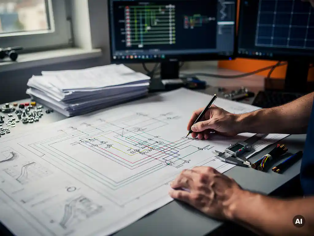
To size cables using a solar wiring diagram, you read the diagram to identify each cable segment, then apply the relevant current rating, voltage drop limit, and short-circuit protection requirements to select the correct cross-section for each run. The wiring diagram acts as your map, showing where each cable connects, what current it carries, and how long each run is. The sections below walk through every key question engineers face when translating a solar wiring diagram into correctly sized conductors.
What factors determine cable size in a PV system?
Cable size in a PV system is determined by four core factors: the maximum continuous current the cable must carry, the allowable voltage drop across the run, the ambient temperature and installation method, and the short-circuit current the cable must withstand without damage. All four must be evaluated together: sizing for current alone is one of the most common errors in PV cable design.
The maximum continuous current is typically calculated as 1.25 times the module’s short-circuit current (Isc) for DC string cables, reflecting the requirement to account for irradiance conditions that can exceed standard test conditions. Voltage drop is usually limited to 1% on the DC side per string run and 1.5% on the AC side, though project specifications sometimes tighten these thresholds.
Installation method matters significantly. A cable buried in the ground dissipates heat differently than one clipped to a cable tray in direct sunlight. Standards such as IEC 60364 and NEC 690 provide correction factors for temperature and grouping that directly affect the minimum permissible cross-section. Ignoring these correction factors leads to undersized cables that overheat under real operating conditions.
How does a solar wiring diagram show cable sizing information?
A solar wiring diagram communicates cable sizing information through conductor labels, cross-section annotations, and color-coded line types that distinguish DC string cables, DC main cables, and AC output cables. Each cable segment on the diagram is typically annotated with its cross-section in mm² (or AWG in North American projects), the number of conductors, and sometimes the cable length.
On a well-structured single-line diagram (SLD), you will find the following sizing-relevant data presented alongside each cable segment:
- Conductor cross-section (e.g., 4 mm², 6 mm², 16 mm²)
- Cable type and insulation rating (e.g., PV1-F for DC, XLPE for AC)
- Number of conductors and polarity
- Approximate cable run length, used to verify voltage drop
- Overcurrent protection device rating at each transition point
The diagram also shows the system topology: how many strings feed each combiner box, how many combiner boxes feed each inverter, which directly determines the cumulative current at each downstream cable segment. Reading the diagram from the module level toward the grid connection point reveals how current aggregates and how cable cross-sections must increase accordingly.
How do you calculate the correct cable cross-section for DC strings?
To calculate the correct DC string cable cross-section, start with the string’s short-circuit current (Isc), multiply it by 1.25 to get the design current, then select a cable cross-section rated for that current under the actual installation conditions. Verify that the resulting voltage drop across the string cable length stays within the 1% limit before finalizing the selection.
The step-by-step process looks like this:
- Determine design current: Multiply the module Isc by 1.25. For a module with Isc = 10 A, the design current is 12.5 A.
- Apply correction factors: Adjust for ambient temperature and installation method using the relevant standard’s derating tables. A cable in a hot roof space may need to be derated by 20% or more.
- Select cross-section from current tables: Choose the smallest cross-section whose rated current, after derating, still exceeds the design current. Common DC string cable sizes are 4 mm² or 6 mm².
- Check voltage drop: Use the formula V_drop = (2 × L × I × ρ) / A, where L is the one-way cable length in meters, I is the design current, ρ is the resistivity of copper (approximately 0.0175 Ω·mm²/m), and A is the cross-section in mm². If the drop exceeds 1%, increase the cross-section.
- Confirm short-circuit withstand: Verify the selected cable can survive the prospective short-circuit current for the duration of the protection device’s clearing time.
In practice, voltage drop is often the binding constraint on longer string runs, particularly in utility-scale ground-mount projects where string cables may run 50 meters or more from the module row to the combiner box.
What’s the difference between DC string cables and AC output cables?
DC string cables carry the output of a single string of modules from the array to the combiner box or inverter input, while AC output cables carry the inverter’s converted output to the AC distribution board or grid connection point. The key differences lie in voltage level, current magnitude, cable type, and the applicable standards governing each.
DC string cables
DC string cables operate at the string’s open-circuit voltage (Voc), which in utility-scale systems can reach 1000 V or 1500 V DC. They must be rated for DC use specifically; standard AC cables are not suitable because DC arcing behavior is fundamentally different from AC. The most common cable type is PV1-F or equivalent, rated for outdoor UV exposure, double insulation, and the relevant DC voltage class. Cross-sections are typically 4 mm² to 6 mm² for individual strings.
AC output cables
AC output cables carry significantly higher currents than individual string cables because they aggregate the output of all strings connected to an inverter. A 100 kW inverter operating at 400 V three-phase produces a full-load current of approximately 144 A, requiring a much larger cross-section, often 50 mm² to 95 mm² depending on run length and installation method. AC cables must comply with low-voltage wiring standards (IEC 60364 or NEC) rather than PV-specific standards, and they require proper overcurrent protection at the inverter output.
What are the most common cable sizing mistakes in solar designs?
The most common cable sizing mistakes in solar designs are failing to apply temperature derating, ignoring voltage drop on long DC runs, using AC-rated cables on the DC side, and sizing AC output cables based on inverter rated power rather than maximum output current. Each of these errors can cause overheating, energy losses, or safety failures that only become apparent after commissioning.
Here is a breakdown of the mistakes engineers encounter most frequently:
- No temperature derating: Cables installed in conduit, on rooftops, or in cable trays exposed to direct sun operate at elevated temperatures. Using the base current rating without applying derating factors leads to cables that are thermally overloaded in real conditions.
- Underestimating voltage drop on long runs: In large ground-mount systems, string cable runs of 40 to 80 meters are common. A 4 mm² cable that passes the current check can still produce a 2% to 3% voltage drop on a long run, cutting into annual yield.
- Using standard AC cables on the DC side: AC cables are not rated for the DC voltage levels or the arc-fault behavior of PV systems. This is both a performance and a safety issue.
- Ignoring cable grouping effects: When multiple cables are bundled together in a tray or conduit, mutual heating reduces each cable’s current-carrying capacity. Grouping correction factors must be applied.
- Sizing AC cables from kW rather than amperes: Power factor and efficiency losses mean the actual AC current is higher than a simple kW-to-ampere conversion at unity power factor would suggest.
How can solar design software automate cable sizing from the wiring diagram?
Solar design software automates cable sizing by reading the system topology directly from the wiring diagram, applying the relevant current, voltage drop, and derating calculations automatically, and outputting a cable schedule with recommended cross-sections for every segment. This eliminates the manual spreadsheet work that typically consumes hours of engineering time per project.
When cable sizing is integrated into the design environment, any change to the system, a different module, a revised string configuration, or a longer cable route, triggers an automatic recalculation across all affected segments. Engineers no longer need to manually trace every downstream impact of a design revision.
This is exactly the workflow that Virto Solar has built into Virto.CAD. Working directly inside AutoCAD and BricsCAD, Virto.CAD automates string planning, cable sizing calculations, and single-line diagram generation within the CAD environment engineers already use. When module specifications change or a string layout is revised, the software recalculates cable cross-sections and updates the SLD automatically, removing the rework cycle that makes manual cable sizing so time-consuming on large C&I and utility-scale projects.
If you want to see how automated cable sizing fits into a full engineering workflow, get in touch with our team to discuss your project requirements.
Frequently Asked Questions
What is the minimum cable cross-section recommended for DC string cables in residential vs. utility-scale PV systems?
For residential rooftop systems, 4 mm² is the most common DC string cable cross-section, as string runs are typically short and currents are modest. In utility-scale ground-mount systems, 6 mm² is often the practical minimum once voltage drop over longer runs is factored in, and some designs step up to 10 mm² on the longest string runs to keep losses within the 1% threshold. Always verify both the current-carrying capacity and the voltage drop result before finalizing the selection — the binding constraint shifts depending on run length.
How do I handle cable sizing when multiple strings share the same conduit or cable tray?
When multiple cables share a conduit or tray, you must apply grouping (bundling) correction factors from your applicable standard — IEC 60364-5-52 or NEC 310 — which reduce each cable’s effective current-carrying capacity due to mutual heating. For example, grouping six cables together can reduce the rated current by 30% or more depending on the installation method, which may require you to step up to the next cross-section. Always determine the total number of current-carrying conductors in the group before selecting the cross-section, and document the correction factors applied so the design can be reviewed and verified.
Can I use the same cable cross-section throughout an entire string run, or does it need to change along the route?
In most residential and small commercial systems, a single cross-section is used for the entire string run because the current is constant from the first module to the inverter input. However, in larger systems where part of the string cable runs through a hotter environment — such as a roof space — and another section runs in a cooler conduit, you may need to apply different derating factors to each section and potentially use a larger cross-section for the thermally constrained portion. Documenting each installation method segment separately in your cable schedule is good practice and makes design reviews straightforward.
What happens if I slightly undersize a DC cable — will the system still work, or will there be an immediate failure?
An undersized DC cable will typically not cause an immediate, visible failure — the system will appear to operate normally at first. The real consequences are gradual: the cable runs hotter than its rated temperature, accelerating insulation degradation and increasing the risk of arc faults or ground faults over time, while the higher resistance also increases resistive losses and reduces annual energy yield. In worst-case scenarios, particularly during peak summer irradiance combined with high ambient temperatures, thermal overload can damage insulation and create a fire risk. This is why applying all derating factors at the design stage, rather than relying on safety margin assumptions, is essential.
How do I size the cable between a combiner box and the inverter DC input?
The combiner-to-inverter DC cable carries the aggregated current of all strings connected to that combiner box, so the design current is the sum of each string’s design current (1.25 × Isc per string, multiplied by the number of strings). Apply the same temperature and grouping correction factors relevant to that cable’s installation method, then check voltage drop over the full run length using the same formula used for string cables. This segment often requires a significantly larger cross-section — 16 mm², 25 mm², or 35 mm² are common — and is frequently the most cost-sensitive cable sizing decision in a combiner-based system layout.
Do cable sizing rules change when designing for 1500 V DC systems compared to 1000 V DC systems?
The current-carrying capacity and voltage drop calculations follow the same methodology regardless of system voltage, but the 1500 V DC rating introduces stricter requirements for cable insulation class, connector ratings, and overcurrent protection devices — not all cables rated for 1000 V DC are approved for 1500 V DC use, so always verify the cable’s voltage rating against the system’s maximum open-circuit voltage including temperature correction. On the positive side, higher system voltage means lower string currents for the same power output, which can allow smaller cross-sections on string cables and reduce resistive losses — one of the primary reasons utility-scale projects have migrated toward 1500 V DC architectures.
How should cable sizing be documented in the project deliverables so it can be reviewed and approved by an inspector or client?
Cable sizing should be documented in a cable schedule that lists every segment from the wiring diagram alongside its design current, correction factors applied, selected cross-section, rated current after derating, and calculated voltage drop — making it straightforward for a reviewer to verify each decision without having to reconstruct the calculation. The cable schedule should reference the specific standard clauses or tables used for derating factors, and it should cross-reference cable segment labels that appear on the single-line diagram so the document set is fully traceable. Including a summary of total DC-side and AC-side voltage drop as a percentage of system voltage gives inspectors and clients a quick top-level check before diving into segment-level detail.
Related Articles
This content was generated with the help of AI — it may contain mistakes
Source link