

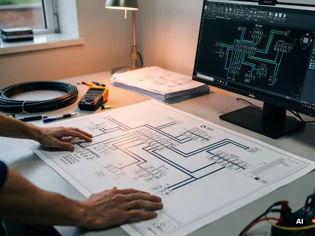
A construction-ready solar wiring diagram includes every electrical detail a licensed installer or contractor needs to build the system without requesting additional information. That means module layouts, string configurations, conductor sizing, conduit routing, protection devices, and labeling that meets local electrical code requirements. The sections below break down each element in detail, from the basics of what makes a diagram truly construction-ready to how modern software can generate these documents automatically.
What makes a solar wiring diagram ‘construction-ready’?
A solar wiring diagram is construction-ready when it contains enough electrical, mechanical, and code-compliance information for a qualified electrician or inspector to install and approve the system without needing clarification from the design team. It is not a schematic sketch or a sales illustration; it is a legally referenced engineering document that drives procurement, installation, and commissioning decisions.
The distinction matters because incomplete diagrams are one of the most common causes of project delays. When a diagram is missing conductor ampacity ratings, grounding details, or equipment model numbers, installers either stop work to request revisions or make assumptions that can fail inspection. A truly construction-ready diagram eliminates both risks by being self-sufficient on the page.
For commercial, industrial, and utility-scale projects, construction-ready status typically also means the diagram has been stamped or reviewed by a licensed professional engineer, references the applicable electrical codes, and aligns with the specifications submitted to the authority having jurisdiction. The diagram must be consistent with the bill of materials, the site layout plan, and any interconnection agreement requirements from the utility.
What components must appear on a solar wiring diagram?
A complete solar wiring diagram must include PV modules with string groupings, combiner boxes or string inverters, DC and AC disconnect switches, inverters, metering equipment, the point of interconnection, all conductor sizes and types, conduit routing, overcurrent protection devices, and grounding and bonding connections. Each component must be identified by manufacturer model number or specification, not just a generic label.
Beyond the core electrical components, the diagram should also show:
- Module specifications: Voc, Isc, Vmp, and Imp values at standard test conditions and temperature-corrected values for the site’s climate
- String configuration details: number of modules per string, number of strings per combiner or inverter input, and polarity markings
- Conductor sizing: wire gauge, insulation type, voltage rating, and maximum current capacity for every circuit segment
- Overcurrent protection: fuse or breaker ratings at each protection point, including string-level fusing where required
- Grounding system: equipment grounding conductors, grounding electrode conductors, and system grounding points
- Disconnects and switchgear: DC and AC disconnects with voltage and current ratings, lockable provisions, and location references
- Utility interconnection: meter socket, point of common coupling, and any utility-required isolation devices
Missing any of these elements typically results in a plan check rejection or a failed inspection, both of which add cost and delay to the project timeline.
What is included in a solar single-line diagram versus a full wiring diagram?
A solar single-line diagram (SLD) is a simplified schematic that represents the electrical system using single lines instead of showing every individual conductor. It communicates the overall system architecture, equipment sequence, and protection scheme in a compact, readable format. A full wiring diagram goes further, showing every conductor, its routing path, physical termination points, and installation-specific details like conduit fill and wire management.
Both documents serve different audiences and purposes within the same project:
What the single-line diagram covers
The SLD is the primary document for utility interconnection applications, permit submissions, and engineering reviews. It shows the logical flow of power from the PV array through the inverter, disconnect switches, metering, and into the grid. Equipment ratings, protection coordination, and system voltage levels are all visible at a glance. Inspectors and utility engineers use the SLD to verify that the system design meets code and interconnection requirements without needing to trace individual conductors.
What the full wiring diagram adds
The full wiring diagram is the document installers work from in the field. It adds physical routing information, conduit schedules, wire color coding, terminal block assignments, and junction box locations. For large commercial or utility-scale systems, the full wiring diagram may span multiple sheets covering the DC array wiring, the AC collection system, the inverter room layout, and the medium-voltage switchgear. Both documents are typically required for a complete permit package on projects above a certain system size, though requirements vary by jurisdiction.
How does string configuration affect wiring diagram complexity?
String configuration directly determines how many circuits, protection devices, and conductor runs appear on a solar wiring diagram. A system with many short strings feeding individual string inverters produces a different diagram structure than one with long strings feeding a central inverter through combiner boxes. The more strings a system has, and the more varied their lengths or orientations, the more complex and detailed the wiring diagram becomes.
In utility-scale projects, string configuration decisions cascade through the entire diagram. Choosing between string inverters and central inverters changes the number of combiner boxes, the DC cable routing topology, and the number of overcurrent protection points that must be shown. Mixing string lengths to accommodate irregular roof shapes or shading obstructions adds annotation complexity because each non-standard string must be individually documented with its specific Voc and Isc values.
Temperature-corrected voltage calculations are also part of this complexity. The diagram must confirm that the maximum open-circuit voltage of every string stays within the inverter’s and equipment’s rated input voltage across the full temperature range expected at the site. When strings of different lengths exist in the same array, each configuration must be verified and documented separately, which multiplies the annotation work required to keep the diagram construction-ready.
What labeling and annotation standards apply to construction-ready PV diagrams?
Construction-ready PV wiring diagrams must follow the labeling requirements of the applicable electrical code, typically the National Electrical Code (NEC) in the United States or IEC standards in European and international markets. At minimum, every circuit, conductor, disconnect, and piece of equipment must carry a label that identifies its rating, function, and location reference so that anyone working from the diagram can locate and verify each element in the field.
Standard annotation requirements for a construction-ready solar wiring diagram include:
- Wire tags and circuit identifiers: unique identifiers for each conductor that match the diagram to physical labels installed in the field
- Equipment nameplates: manufacturer, model number, and key ratings (voltage, current, power) for every major component
- Conduit and raceway schedules: conduit type, trade size, fill percentage, and routing reference for each run
- Warning and caution labels: required NEC or IEC warning labels for DC voltage, dual power sources, and rapid shutdown systems
- Revision block and title block: project name, address, designer name and credentials, revision history, and drawing number
- Code references: citations to the specific code sections that govern the design decisions shown on the diagram
Annotation standards also vary by the authority having jurisdiction. Some municipalities require specific label formats, font sizes, or additional notes that go beyond the base code. Checking local requirements before finalizing the diagram prevents revision cycles during plan check.
How can solar design software automate wiring diagram generation?
Solar design software automates wiring diagram generation by linking the system’s electrical parameters directly to the drawing output. When a designer inputs module specifications, inverter selection, and string configuration, the software calculates conductor sizing, protection ratings, and voltage values automatically, then places them on the diagram without manual data entry. Changes to any input parameter propagate through the entire diagram instantly, eliminating the rework cycle that plagues manual workflows.
This automation is particularly valuable for construction-ready documentation because it removes the most error-prone step in the process: transcribing calculated values from a spreadsheet into a CAD drawing. In traditional workflows, an engineer calculates string voltage in Excel, then manually types that value into AutoCAD. If the module changes, both the spreadsheet and every affected drawing must be updated by hand. Automated software keeps these in sync by design.
Our Virto.CAD plugin for AutoCAD and BricsCAD takes this approach further by working directly inside the CAD environment engineers already use. String planning, cable sizing, single-line diagram generation, and bill of materials output are all handled within the same tool, so there is no data transfer between applications and no opportunity for transcription errors. A design that would previously take days of manual drawing and checking can be completed in a fraction of the time, with every annotation and label generated from the underlying electrical model rather than typed in manually.
For engineering teams looking to move away from disconnected spreadsheet and CAD workflows, getting in touch with our team is a practical first step to understanding how automation fits into your specific project types and permitting requirements.
Frequently Asked Questions
How do I know if my solar wiring diagram will pass plan check on the first submission?
Before submitting, cross-check your diagram against the checklist of required components — string configurations, conductor sizing, overcurrent protection, grounding details, and equipment model numbers — and verify that every element matches the bill of materials and site layout plan. Confirm that all labeling meets both the base NEC or IEC requirements and any additional local amendments enforced by your authority having jurisdiction (AHJ), since municipal-specific requirements are a common source of first-submission rejections. Using design software that auto-generates annotations from the electrical model significantly reduces the risk of mismatched or missing values.
What are the most common mistakes engineers make when creating solar wiring diagrams?
The most frequent mistakes include omitting temperature-corrected voltage calculations, using generic equipment labels instead of specific manufacturer model numbers, and failing to update all affected drawings when a component changes mid-design. Another common error is inconsistency between the single-line diagram and the full wiring diagram — for example, showing different conductor sizes or protection ratings across the two documents. These discrepancies are easy to introduce in manual workflows where values are transcribed by hand, and they are among the first things inspectors and utility engineers look for during review.
Do residential solar installations require the same level of wiring diagram detail as commercial projects?
Residential systems generally require less documentation than commercial or utility-scale projects, but they still need a code-compliant single-line diagram showing string configuration, conductor sizing, overcurrent protection, disconnect locations, and the point of interconnection. The key difference is that residential permits typically do not require a professional engineer stamp, whereas commercial and utility-scale projects almost always do. However, AHJ requirements vary significantly — some municipalities apply commercial-grade documentation standards even to residential rooftop systems, so always verify local permit requirements before finalizing your drawing package.
How should I handle wiring diagrams when modules or inverters are substituted after the original design is approved?
Any equipment substitution that changes electrical parameters — such as a different module with a higher Voc or an inverter with a different input voltage range — requires a formal diagram revision and, in most cases, a resubmission to the AHJ before installation can proceed. Update all affected annotations, recalculate temperature-corrected string voltages, and verify that conductor sizing and protection ratings still comply with the new equipment specifications. Keeping a clear revision block on every drawing sheet with dated change descriptions is essential for maintaining a traceable record that inspectors and utility engineers can follow.
What is rapid shutdown, and how does it affect what appears on a solar wiring diagram?
Rapid shutdown is an NEC requirement (Section 690.12) that mandates PV systems on buildings be equipped with a means to reduce conductors’ voltage to a safe level for first responders in an emergency. On a wiring diagram, this means you must show the rapid shutdown initiator device, its wiring to the array-level module-level power electronics or boundary equipment, and the required NEC warning labels indicating the system has rapid shutdown capability. The specific equipment and wiring details depend on whether the system uses module-level power electronics (microinverters or DC optimizers) or a string inverter with a dedicated rapid shutdown device, so the diagram must clearly reflect whichever approach is installed.
How do I correctly document a solar system with multiple roof orientations or tilt angles on a wiring diagram?
Each sub-array with a distinct orientation or tilt must be documented separately, including its own temperature-corrected Voc and Isc values, because shading profiles and irradiance levels differ across orientations. On the wiring diagram, clearly delineate which strings belong to each sub-array and ensure they are connected to compatible inverter inputs — most modern string inverters support multiple maximum power point trackers (MPPTs) for exactly this purpose. Annotate each MPPT input with the corresponding string count, module count per string, and electrical parameters so that installers can verify correct terminations in the field without ambiguity.
Can solar design software handle utility-scale projects with hundreds of strings, or is it only practical for smaller systems?
Modern solar design software, including CAD-integrated tools, is built to scale to utility-scale complexity — managing hundreds of strings, multiple combiner boxes, central inverters, and medium-voltage collection systems within a single coordinated model. The efficiency advantage of automation actually grows with system size: manually maintaining consistent annotations across dozens of drawing sheets for a multi-megawatt project is where transcription errors and version-control problems are most costly. The key is choosing a tool that keeps the electrical model, the wiring diagrams, and the bill of materials in sync automatically, so that a single design change propagates correctly across the entire drawing set rather than requiring manual updates sheet by sheet.
Related Articles
This content was generated with the help of AI — it may contain mistakes
Source link