


Contributed by Archit Patnaik, PE, PMP | Senior project manager, Pure Power Engineering
Edited by Paul Gerke
How a County of Maui water portfolio in Hawaiʻi used circular concrete storage tanks as low-tilt solar platforms after solving the non-penetration, circular-layout, wind-ballast, and maintenance-access constraints that set tank-mounted PV apart from an ordinary rooftop.
For most drinking-water utilities, pumping is the dominant electrical load; the U.S. Environmental Protection Agency (EPA) notes that roughly 80% of municipal water processing and distribution costs are for electricity, and that energy is often the largest controllable operating cost, on the order of 25–30% of operation and maintenance (O&M). Flat, sunlit land sitting idle next to that load is scarce, especially on islands.
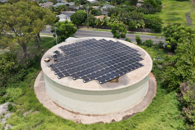
A County of Maui water utility addressed both at once by mounting low-tilt, non-penetrating PV arrays of roughly 105 to 141 kilowatt (kW)-DC on the roofs of its circular concrete storage reservoirs, sited at the same facilities whose electrical load they help offset. The portfolio was delivered with Johnson Controls as the program contractor.
Across the portfolio, the same approach was applied to reservoir roofs at multiple sites, putting generation on land the utility already owned and maintained while serving wells, booster stations, and treatment loads. The question was never whether solar would fit on a tank; it was how to do it without penetrating the roof, overloading the structure, blocking inspection access, or taking the reservoir out of service.
A containment vessel is not a roof deck
On a water tank, the design avoids penetrating the roof, so the array is ballasted, held down by weight rather than fasteners. That makes weight the governing question. Solar is light, so what matters is how much ballast the tank can carry, and that hinges on seismic behavior more than on the roof itself. Because these reservoirs are decades old, their capacity is established up front with a structural engineer, from original drawings or field evaluation, before a single panel goes up.
Fitting a rectangle onto a circle
PV modules and racking come in rectangular blocks; reservoir roofs are circular. The array must be packed into the inner disc while holding setbacks from the curved edge and clearing the features the tank still needs in service: access hatches, vents, and inspection points. Maximizing capacity inside that circle while preserving the perimeter and keep-out zones is the defining layout exercise of a tank-mounted system, which is why these arrays read as a dense rectangular field stepped in at the edges rather than a tidy rectangle.

The layout also had to satisfy rooftop-PV fire-service access requirements. Its design held a minimum four-foot clear perimeter pathway around the array and four-foot clearance around each roof access hatch, per the access-pathway provisions for flat roofs in the 2018 International Fire Code, Section 1204.3 (2018 IFC, Chapter 12).
The baseline perimeter is six feet; under the Section 1204.3.1 exception, where either axis of the structure is 250 feet or less, the perimeter may be reduced to four feet, which applies here, recovering usable roof area without compromising access.
Wind and ballast are a single coupled problem
Tanks are tall and usually sit on high, open ground, exactly where wind loads are highest. A ballasted array resists uplift with weight, so the obvious answer is more ballast. But mass cuts both ways: the same weight that holds the panels down in a windstorm drives lateral force under seismic loading, and the heavier the array, the more it loads the tank in an earthquake. That balance is tighter on a tank than on an ordinary building, because the water it holds reacts during an earthquake and adds its own lateral force, so the tank is already carrying a heavy seismic demand before any ballast is added. The limit, then, isn’t the roof’s gravity capacity; the panels are light and largely displace the foot-traffic live load the roof was already designed for. The binding constraint is how much added seismic load the ballast may impose on a tank that is already seismically loaded by its contents.
So wind and seismic have to be solved together, not in sequence. Ballast is sized to resist the site’s wind uplift (per the American Society of Civil Engineers load standard, ASCE 7), then checked to confirm the added mass hasn’t pushed the seismic case past its limit, and the two are reconciled iteratively. Keeping the modules low and flat helps at both ends: a lower profile catches less wind, which means less ballast is needed in the first place.
Keeping the reservoir serviceable
A PV array lasts decades; the reservoir beneath it is expected to serve far longer and cannot be allowed to fail because solar got in the way. The EPA identifies open access hatches and broken vent screens as sanitary risks for finished-water storage, the very features a rooftop array could obstruct or damage if laid out carelessly. On a finished-water reservoir, keeping that access clear is not just a maintenance convenience; it is part of sanitary protection and inspection readiness. So access hatches, vents, and inspection points stay clear, and the layout preserves corridors for eventual interior inspection and recoating. Because flat tank roofs pond, modules and conduit are routed and supported to stay clear of low spots rather than trap water against the structure.
Power leaves the tank without burdening the structure. The inverter, disconnects, and panelboard sit on a freestanding rack at grade beside the tank rather than on the wall, keeping the heavy equipment off the structure. The conductors do run down the wall, but in conduit fastened with anchors chosen to suit the tank’s construction, so the attachment respects how that particular wall is built. The array’s output is carried down to the inverters at grade.

What it delivers
Treated as a repeatable method rather than a one-off, tank-mounted PV converts infrastructure a utility already owns into distributed generation that offsets a large share of the facility’s electrical load and lowers the operating cost of critical water service. The discipline is consistent from site to site: structural assessment first, a ballasted non-penetrating array, wind and ballast as one coupled calculation, the array optimized inside the circular footprint, and the tank’s own maintenance functions protected as a first-order requirement.
The broader takeaway is that the most valuable solar real estate is sometimes already built. A reservoir roof is not free ground; it is a containment structure with strict rules, but for a utility short on land and long on pumping load, the asset that holds the water can also be the best place to make the power that moves it.
About the Author

Archit Patnaik, PE, PMP, is a senior project manager at Pure Power Engineering specializing in solar PV and battery energy-storage systems. He leads electrical engineering for solar and storage projects serving developers, EPCs, and asset owners, and is a NABCEP-certified PV Installation Professional.
Source link