

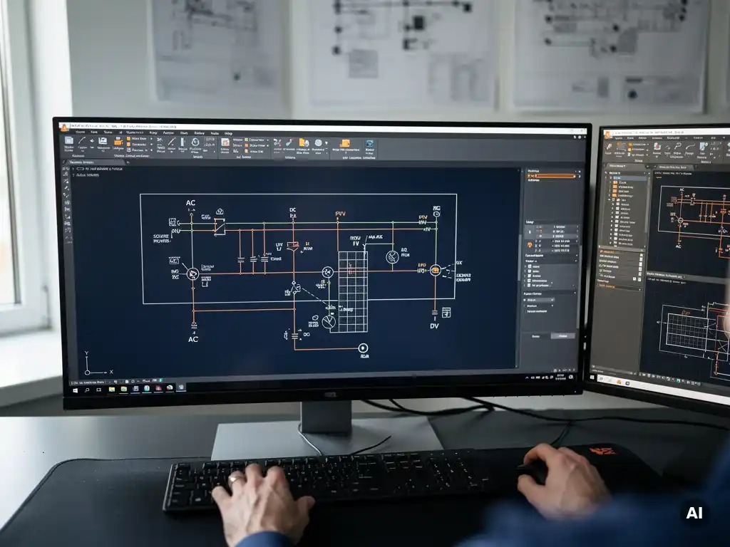
You can automate single-line diagram creation in AutoCAD by using a dedicated solar design plugin that reads your system configuration and generates a fully structured SLD automatically. Instead of drawing each component and connection by hand, the software builds the diagram from your existing design data, including string layouts, inverter selections, and cable sizing. Below, we answer the most common questions engineers have about how this process works in practice.
What makes single-line diagram creation so time-consuming in AutoCAD?
Creating a solar wiring diagram manually in AutoCAD is slow because every component, connection, and label must be placed individually, and any change to the system design forces you to redo large portions of the drawing from scratch. For a commercial or utility-scale project, a single SLD can take several hours to produce, and that time multiplies quickly across design revisions.
The core problem is that a standard AutoCAD environment has no awareness of your PV system. It treats a solar inverter the same way it treats any other block, so there is no automatic relationship between your module layout, your string configuration, and the diagram that documents it. When a client requests a different inverter, or the module count changes, the SLD does not update. You redraw it.
This creates a painful cycle for PV engineers. String configuration changes trigger cable sizing recalculations, which affect the SLD, which must then be redrawn and re-annotated. Every revision is a manual process, and every manual step introduces the risk of inconsistency between the layout drawing and the electrical diagram. For large-scale projects with dozens of inverters and hundreds of strings, this is not a minor inconvenience. It is a genuine bottleneck that delays project delivery.
How does automated SLD generation work in CAD-based solar software?
Automated SLD generation works by linking the electrical diagram directly to the system design data. When you configure strings, select inverters, and define cable routes in a CAD-based solar design tool, the software stores all of that information in a structured model. The SLD is then generated from that model rather than drawn by hand, so it always reflects the current state of the design.
In practice, this means the software reads your string planning output, knows which modules connect to which combiner or inverter input, understands the DC and AC topology, and uses that information to construct the diagram automatically. Component symbols are placed according to the actual system hierarchy, and labels such as cable cross-sections, fuse ratings, and circuit identifiers are populated from the calculated values rather than typed manually.
When the design changes, the SLD updates accordingly. If you swap an inverter model or adjust the number of strings per MPPT input, the diagram reflects that change without requiring you to touch the drawing directly. This is the fundamental shift that automation introduces: the SLD becomes an output of the engineering process rather than a separate manual task running alongside it.
What components are automatically included in a generated solar SLD?
A well-implemented automated solar wiring diagram typically includes all major DC and AC electrical components: PV modules grouped by string, string combiners or DC junction boxes, DC cables with cross-section annotations, inverters, AC cables, protection devices such as fuses and surge arresters, the AC distribution board or transformer connection, and grid connection points.
Beyond the physical components, the diagram also carries calculated values that engineers would otherwise enter manually. These include string voltages, maximum current ratings, cable lengths, and protection device specifications. In a CAD-based solar design environment, these values come directly from the engineering calculations already performed during the design phase, so there is no re-entry and no risk of the SLD showing values that differ from the rest of the project documentation.
Component symbols follow standard electrical drawing conventions, and the layout of the diagram reflects the actual system hierarchy from the module level through to the point of grid connection. For projects using multiple inverter types or hybrid configurations, the software handles each branch of the system independently while keeping the overall diagram coherent and readable.
Does automated SLD creation work for both rooftop and utility-scale projects?
Yes, automated SLD creation works for both commercial rooftop and utility-scale ground-mounted projects, though the complexity of the output scales significantly with project size. For a rooftop installation with one or two inverters, the generated diagram is straightforward. For a utility-scale plant with multiple combiner boxes, central inverters, and MV transformer connections, the software must handle a much deeper electrical hierarchy, and a capable tool manages this without requiring manual intervention.
The key factor is whether the underlying software is designed for large-scale PV engineering or adapted from a general-purpose tool. Platforms built specifically for commercial and utility-scale solar, like Virto Solar’s design suite, handle the full range of project types within the same workflow. The string planning, cable sizing, and SLD generation all operate on the same data model regardless of whether the project covers 500 square metres of rooftop or 50 hectares of ground-mounted arrays.
For utility-scale projects in particular, automated SLD generation offers the greatest return. The sheer number of strings, combiner boxes, and inverter connections makes manual diagramming impractical at speed, and the risk of errors in a hand-drawn SLD increases proportionally with system size.
How much time can automating SLD creation actually save?
Automating SLD creation typically eliminates several hours of drawing time per project, and for large utility-scale designs, the savings can extend to days. When SLD generation is integrated into a broader automated design workflow, the cumulative time reduction across string planning, cable sizing, and documentation can reduce total engineering time by around 80% compared to fully manual processes.
The savings come from two sources. The first is the direct time eliminated by not drawing the diagram by hand. The second, often larger source, is the time saved on revisions. A manually drawn SLD must be updated every time the design changes. An automatically generated one simply regenerates. On a project that goes through five or six design iterations before sign-off, that difference compounds quickly.
There is also a less obvious benefit: the time engineers currently spend checking for consistency between the SLD and other project documents. When the diagram is generated from the same data as the layout and calculations, that checking step becomes much shorter because the risk of discrepancy is structurally removed rather than managed after the fact.
What’s the best tool for automating single-line diagrams in AutoCAD?
The best tool for automating single-line diagrams in AutoCAD is one that operates as a native plugin within the CAD environment, integrates SLD generation with the rest of the engineering workflow, and handles the full complexity of commercial and utility-scale PV projects without requiring data to be re-entered or transferred between platforms.
Virto.CAD meets these criteria directly. It runs inside AutoCAD and BricsCAD, which means engineers stay in the environment they already know and use daily. String planning, cable sizing, shading analysis, and SLD generation all work from the same project data, so the diagram is always consistent with the rest of the design. There is no export step, no manual transfer of values, and no separate tool to learn for the electrical documentation.
For EPC firms and engineering consultancies working on C&I and utility-scale projects, this kind of integrated approach is what makes automation genuinely useful rather than just a faster way to do the same manual work. If you want to see how it fits your current workflow, you can speak with our team to discuss your project types and design process in detail.
Frequently Asked Questions
Can I use automated SLD generation if my team already has existing AutoCAD templates and symbol libraries?
Yes, most CAD-native solar design plugins are designed to work alongside existing AutoCAD environments, including custom templates and symbol libraries. Tools like Virto.CAD operate as plugins within AutoCAD and BricsCAD, meaning your existing drawing standards, title blocks, and layer conventions can typically be preserved. It is worth confirming with the software provider that their component symbols and output formatting can be aligned with your internal drafting standards before committing to a full rollout.
What happens to the SLD if I make a last-minute design change just before submitting for permits?
With an automated SLD workflow, a last-minute design change simply triggers a regeneration of the diagram rather than a manual redraw. If you swap an inverter model, adjust string lengths, or update cable sizing the day before submission, the SLD reflects those changes immediately and consistently across all affected labels, ratings, and component connections. This is one of the most practical advantages of automation in real project conditions, where late-stage revisions are common and the cost of an inconsistent submission can be significant.
Do automatically generated SLDs meet the documentation requirements for grid connection applications and authority submissions?
In most cases, yes, provided the software is designed with compliance-ready outputs in mind. A well-implemented automated SLD includes all the component data, protection device ratings, cable specifications, and system hierarchy information that network operators and permitting authorities typically require. However, specific requirements vary by country, region, and utility, so it is good practice to verify that the generated diagram format aligns with your local grid connection or building permit standards before using it in a live submission.
Is there a learning curve involved in switching from manual SLD drafting to an automated plugin workflow?
The learning curve is generally low for engineers already working in AutoCAD or BricsCAD, since a native plugin does not require you to leave your familiar environment or learn an entirely new platform. The main adjustment is shifting from drawing components manually to configuring the system design correctly upfront, knowing that the SLD will be generated from that data. Most teams find that the time invested in learning the tool is recovered within the first one or two projects, particularly if those projects involve multiple design iterations.
Can the automated SLD handle hybrid systems that include battery storage alongside PV generation?
Capable solar design platforms are increasingly built to handle hybrid configurations, including systems that integrate battery energy storage with PV generation. The key requirement is that the software’s underlying data model supports the additional electrical components and topologies involved, such as battery inverters, DC coupling arrangements, and separate protection circuits. If hybrid projects are part of your portfolio, it is worth specifically testing or requesting a demonstration of the tool’s SLD output for a storage-integrated system before adopting it as your standard workflow.
What are the most common mistakes engineers make when first implementing automated SLD generation?
The most common mistake is treating the automated SLD as a shortcut while still relying on manual data entry elsewhere in the workflow. If string configurations, cable sizing, or component selections are not properly defined within the software’s design model, the generated diagram will reflect those gaps or errors directly. The second common mistake is not validating the first few automatically generated diagrams against your internal quality standards before using them in client-facing or regulatory submissions. Automation removes manual drawing effort, but it does not replace engineering judgment in reviewing the output.
How do I get started with automating SLD creation for my current projects?
The most practical starting point is to identify a current or upcoming project that represents your typical workload and use it as a test case for an automated tool. Most providers, including Virto Solar, offer direct consultations where you can walk through your specific project types, design process, and documentation requirements before committing. Running the automated workflow in parallel with your existing manual process on a single project gives you a clear, concrete comparison of time savings and output quality before making a broader change to your team’s workflow.
Related Articles
This content was generated with the help of AI — it may contain mistakes
Source link