

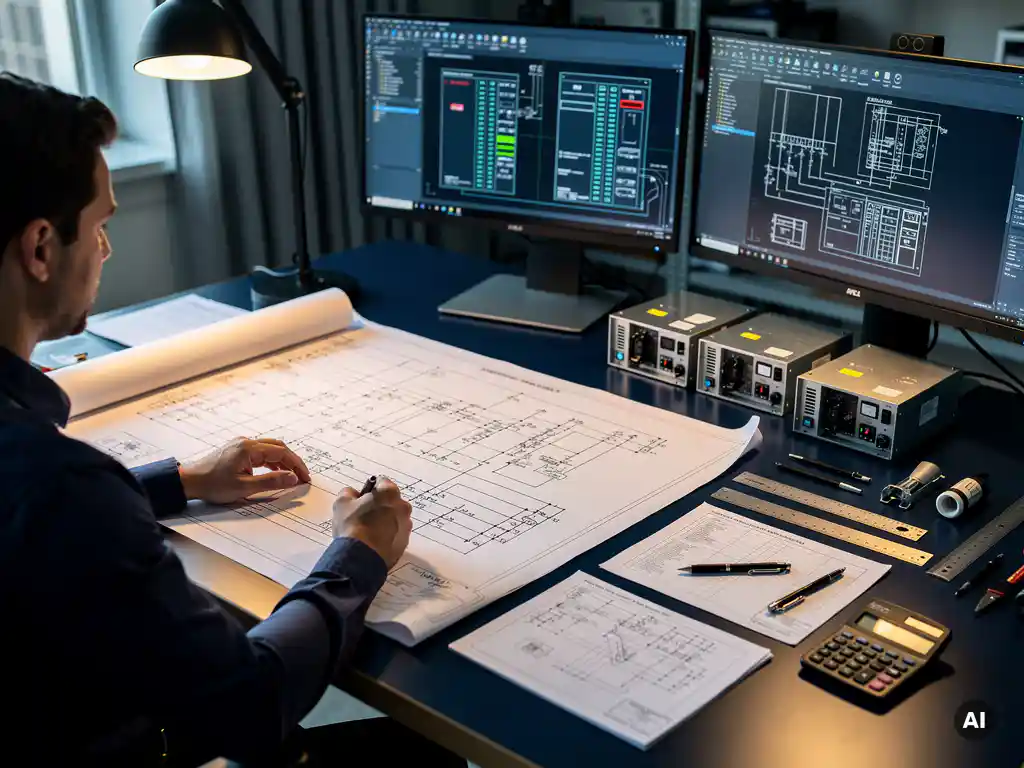
Designing a battery storage system for an EPC project means selecting and integrating the right combination of battery technology, power conversion equipment, and control systems to meet a defined energy and power requirement, then engineering that system to connect safely and reliably with the broader PV plant. The process spans component selection, system sizing, coupling architecture, electrical design, grid compliance, and performance modeling. This article walks through each of those steps in the order an EPC engineer typically encounters them.
What components make up a battery storage system in an EPC project?
A battery energy storage system (BESS) in an EPC project consists of four core layers: the battery modules themselves, a battery management system (BMS), a power conversion system (PCS), and an energy management system (EMS). These layers work together to store energy, protect the cells, convert between DC and AC power, and control dispatch behavior according to project requirements.
At the cell level, lithium iron phosphate (LFP) chemistry dominates utility-scale and commercial EPC projects in 2026 due to its thermal stability, long cycle life, and competitive cost per kilowatt-hour. Cells are grouped into modules, modules into racks, and racks into battery containers or cabinets, the exact configuration depends on the manufacturer and the project’s energy capacity target.
The BMS monitors cell voltage, temperature, and state of charge at the module level, protecting the pack from overcharge, deep discharge, and thermal runaway. Above the BMS sits the PCS, which handles the DC-to-AC conversion (or DC-to-DC in some configurations) and interfaces with the grid or the PV inverter. Finally, the EMS acts as the brain of the system, coordinating charge and discharge cycles based on grid signals, tariff structures, or self-consumption targets.
In large EPC projects, auxiliary systems also matter: fire suppression, HVAC for thermal management, communication gateways (Modbus, CAN bus, IEC 61850), and remote monitoring infrastructure are all part of the full scope of supply.
How do you size a battery storage system for a solar project?
Battery storage sizing for a solar project starts with two independent requirements: the power capacity (in kilowatts or megawatts) needed to meet peak demand or grid export limits, and the energy capacity (in kilowatt-hours or megawatt-hours) needed to cover the required discharge duration. Both must be defined before any equipment can be specified.
The sizing process typically follows these steps:
- Define the use case: Self-consumption maximization, peak shaving, frequency response, and backup power all lead to different sizing outcomes. A peak-shaving application might need high power with short duration; a self-consumption system needs energy capacity matched to overnight load.
- Analyze load and generation profiles: Overlay the PV generation curve against the site load profile to identify surplus energy periods and deficit periods. The gap between generation and consumption defines the storage window.
- Calculate usable energy: Battery capacity is rated at nominal conditions, but usable capacity depends on the depth of discharge (DoD) allowed by the BMS and the degradation buffer built in for end-of-life performance. A system rated at 1,000 kWh with 90% DoD and a 20% end-of-life buffer delivers roughly 720 kWh of usable energy at the start of life.
- Account for round-trip efficiency: Typical lithium battery systems achieve 85 to 92% round-trip efficiency. This loss must be factored into the energy balance when sizing for a specific dispatch target.
- Apply a C-rate check: Confirm that the selected battery capacity can deliver the required power at the intended C-rate without exceeding the manufacturer’s continuous discharge rating.
For utility-scale EPC projects, sizing is often iterative, the initial estimate is refined through energy modeling software and then stress-tested against worst-case irradiance and load scenarios before the final specification is locked.
What’s the difference between AC-coupled and DC-coupled battery storage?
The key difference between AC-coupled and DC-coupled battery storage is where the battery connects in the system. In an AC-coupled configuration, the battery has its own dedicated inverter and connects on the AC bus, independently of the PV inverter. In a DC-coupled configuration, the battery connects directly on the DC side, sharing the same inverter as the PV array or using a DC-DC converter before a combined inverter.
AC-coupled battery storage
AC coupling is the most common approach in retrofit and commercial EPC projects because it allows a battery system to be added to an existing PV installation without modifying the original DC wiring or inverter. Each component operates independently, which simplifies fault isolation and allows the battery to charge from the grid as well as from the PV array. The trade-off is an additional conversion loss: energy from the PV array passes through the PV inverter (DC to AC), then through the battery inverter again (AC to DC) during charging, and back through the battery inverter (DC to AC) during discharge. This double conversion reduces overall system efficiency compared to DC coupling.
DC-coupled battery storage
DC coupling avoids the double conversion loss by connecting the battery directly on the DC bus, typically through a bidirectional DC-DC converter. This architecture is more efficient and better suited to new-build utility-scale projects where the system is designed from scratch. It also allows the battery to capture energy that would otherwise be clipped by the inverter during periods of high irradiance, improving overall yield. The complexity is higher, however: the DC-DC converter and the main inverter must be carefully coordinated, and the DC voltage windows of the battery and PV array must be compatible.
For EPC engineers, the choice between AC and DC coupling is usually driven by whether the project is a greenfield design or a retrofit, the inverter topology selected, and the project’s efficiency targets.
What are the key electrical design considerations for BESS integration?
Integrating a battery energy storage system into a PV plant introduces several electrical design challenges that go beyond standard PV engineering. The most critical considerations are protection coordination, cable sizing for bidirectional current flow, DC bus voltage compatibility, and earthing strategy.
Protection coordination is more complex in a BESS-integrated system because fault current can flow from multiple sources simultaneously, the grid, the PV array, and the battery. Overcurrent protection devices must be selected and coordinated to clear faults without causing nuisance tripping or leaving parts of the system unprotected during battery discharge.
Cable sizing must account for bidirectional current flow. Unlike a standard PV DC cable that only carries current in one direction, battery DC cables carry charge current and discharge current at potentially different magnitudes. The cable must be rated for the higher of the two, and voltage drop calculations must be performed in both directions.
DC bus voltage compatibility is a frequent design constraint in DC-coupled systems. The battery’s operating voltage window must overlap with the inverter’s MPPT range across the full state-of-charge range. If the battery voltage drops below the inverter’s minimum input voltage at low state of charge, the system will disconnect prematurely.
Earthing and bonding strategy also requires careful attention. Depending on the inverter topology (transformerless or transformer-based) and the battery chemistry, the earthing configuration of the DC side must be designed to prevent leakage currents and ensure safety under fault conditions. This is particularly important in large utility-scale systems where long DC cable runs increase the risk of ground faults going undetected.
Which grid codes and standards apply to battery storage EPC projects?
Battery storage EPC projects must comply with a combination of grid connection codes, product safety standards, and installation regulations that vary by country and utility. The most widely referenced international standards are IEC 62933 (for electrical energy storage systems), IEC 62619 (safety requirements for lithium cells and batteries), and IEC 61850 (communication protocols for energy management). Grid connection requirements are typically defined by the local transmission or distribution system operator.
In Europe, the EU Network Codes, particularly the Requirements for Generators (RfG) regulation, apply to storage systems above certain capacity thresholds and define requirements for reactive power capability, fault ride-through, and frequency response. In the United States, IEEE 1547 governs the interconnection of distributed energy resources including storage, and UL 9540 is the primary product safety standard for energy storage systems.
Beyond the standards themselves, EPC engineers must engage with the grid operator early in the design process to obtain a grid connection agreement that specifies the technical requirements the system must meet. These requirements often include power factor control, ramp rate limits, anti-islanding protection, and remote curtailment capability. Designing to these specifications from the outset avoids costly redesign during commissioning.
Fire safety standards are equally important. NFPA 855 in the US and EN 62485 in Europe set requirements for the installation, spacing, and fire suppression of battery systems. Many insurers and authorities having jurisdiction (AHJs) now require compliance with these standards as a condition of project approval.
How does battery storage affect PV system yield and performance modeling?
Battery storage affects PV system yield and performance modeling in two main ways: it changes the effective energy delivered to the load or grid by introducing round-trip losses, and it can increase the total energy captured from the PV array by absorbing generation that would otherwise be curtailed. Both effects must be accounted for in the energy model to produce an accurate yield forecast.
In a standard PV-only model, any generation that exceeds the inverter’s AC output limit is clipped and lost. In a DC-coupled BESS system, that clipped energy can be redirected into the battery, increasing the total energy harvested from the array. This clipping recovery effect can meaningfully improve annual yield in systems with high DC/AC ratios, a common design choice in utility-scale projects to maximize inverter utilization.
On the loss side, round-trip efficiency (typically 85 to 92% for lithium systems) means that every kilowatt-hour stored and discharged results in a net energy loss. The performance model must include this as a separate loss category, distinct from the PV system losses (soiling, shading, temperature, wiring) that are already accounted for in tools like PVsyst.
Degradation modeling is another layer of complexity. Battery capacity degrades over time, reducing the usable energy available in later project years. A rigorous performance model will apply an annual degradation rate to the battery capacity and recalculate the dispatch behavior year by year to show how self-consumption ratios or peak-shaving effectiveness change over the project lifetime.
For EPC engineers working within AutoCAD or BricsCAD environments, integrating BESS modeling into the broader PV design workflow is where tools like Virto Solar’s design platform can help, connecting the electrical design, yield simulation, and documentation into a single coherent process rather than managing them across separate spreadsheets and software packages. If you want to explore how this fits your specific project setup, get in touch with our team for a conversation tailored to your workflow.
Frequently Asked Questions
How do I choose between a single large BESS container and multiple smaller units for a utility-scale project?
The choice depends on your power and energy targets, site layout constraints, and redundancy requirements. Multiple smaller units offer modularity — if one container goes offline for maintenance or a fault, the rest of the system continues operating — while a single large container typically reduces balance-of-plant costs and simplifies grid connection. For utility-scale EPC projects, most engineers default to containerized modular units in the 2–5 MWh range and stack them to reach the project target, as this approach aligns with standard manufacturer offerings and simplifies spare parts management.
What are the most common mistakes EPC engineers make when integrating a BESS for the first time?
The most frequent mistakes are undersizing the DC cabling for bidirectional current, failing to coordinate protection devices for multi-source fault current, and locking in equipment specifications before receiving the grid operator’s technical connection requirements. Another common oversight is neglecting to model battery degradation in the energy yield forecast, which leads to performance shortfalls in later project years that weren’t anticipated in the original contract. Engaging the grid operator and the BMS/EMS vendor early — before detailed design begins — eliminates most of these issues.
How do I validate that the BMS and EMS from different vendors will communicate and operate correctly together?
Start by confirming that both systems support a common communication protocol — IEC 61850, Modbus TCP, or CAN bus — and request protocol implementation conformance statements (PICS) from each vendor before procurement. During factory acceptance testing (FAT), run a full integration test that simulates real dispatch commands from the EMS and verifies that the BMS responds correctly, including protection triggers and state-of-charge reporting. Don’t assume interoperability based on protocol compatibility alone; vendor-specific register maps and timing behaviors frequently cause integration issues that only surface during commissioning if not tested earlier.
What happens to the battery system during a grid outage — can it continue supplying the site load?
Whether the BESS can supply the site load during a grid outage depends entirely on how the system was designed. A standard grid-tied BESS with anti-islanding protection will disconnect when the grid goes down, just like a standard PV inverter. To enable backup or islanding capability, the system must be specifically designed with a transfer switch, an inverter that supports island mode, and an EMS configured to manage frequency and voltage without grid support. This is a significant design decision that must be defined in the project scope from the outset, as it affects inverter selection, protection design, and grid code compliance.
How should I approach the thermal management design for a BESS in a hot climate?
In high-ambient-temperature environments, thermal management is one of the most critical factors affecting battery longevity and safety. LFP cells perform best within a 15–35°C operating range, and sustained operation above 40°C accelerates degradation and increases thermal runaway risk. EPC engineers should specify active liquid cooling or precision air conditioning for the battery enclosure, size the HVAC system for the worst-case combination of ambient temperature and maximum charge/discharge rate, and ensure the thermal management system is powered by a reliable auxiliary supply that remains active even when the battery is at low state of charge. Always request the manufacturer’s thermal derating curves and incorporate them into your performance model.
At what project scale does it make sense to invest in a full energy management system versus simpler rule-based control?
For small commercial projects below roughly 500 kWh, a rule-based controller built into the inverter or BMS — such as a fixed time-of-use schedule or a self-consumption threshold — is usually sufficient and avoids the cost and complexity of a standalone EMS. Once a project exceeds that threshold, or involves multiple revenue streams (e.g., self-consumption plus frequency response plus demand charge management), a dedicated EMS becomes cost-justified because it can optimize dispatch across competing objectives in real time. At utility scale, an EMS with SCADA integration and remote monitoring is essentially mandatory for grid code compliance and asset management.
How do I account for battery warranty and degradation guarantees when writing EPC contracts?
Battery warranties in EPC contracts should specify a minimum capacity retention guarantee at end of warranty period (typically 70–80% of nameplate capacity after 10 years or a defined number of cycles), along with a clear definition of how capacity will be measured and who bears the cost of a capacity test. Ensure the warranty terms distinguish between calendar degradation and cycle degradation, and confirm that the operating conditions required to maintain the warranty — temperature range, DoD limits, C-rate limits — are achievable within your system design. Misalignment between the warranty conditions and the actual dispatch profile is one of the most common sources of warranty disputes in BESS projects.
Related Articles
This content was generated with the help of AI — it may contain mistakes
Source link