

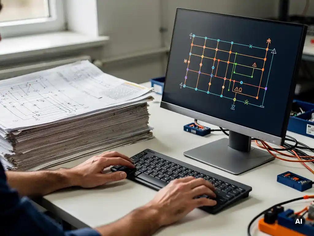
Drawing a solar wiring diagram manually typically takes between one and three days for a single project, depending on system size and complexity. Automated tools can generate the same diagram in minutes. The time gap is not marginal; it is structural, and it compounds across every revision, every module change, and every project handover. This article breaks down exactly where that time goes, why manual drafting carries hidden risks, and when switching to automated tools makes clear engineering sense.
How long does it actually take to draw a wiring diagram manually?
For a commercial or utility-scale PV project, drawing a wiring diagram manually in AutoCAD typically takes between one and three full working days. A straightforward rooftop system with a single inverter and a handful of string runs might take four to six hours. A ground-mounted installation with multiple combiner boxes, DC and AC cable runs, and protection devices can stretch well beyond two days, and that estimate assumes no revisions.
The breakdown looks roughly like this for a mid-size commercial project:
- Laying out the single-line diagram structure: two to four hours
- Manually placing and labeling components (inverters, combiners, disconnects, meters): one to two hours
- Drawing cable routes and annotating wire sizes: two to three hours
- Adding protection devices, earthing symbols, and notation: one to two hours
- Checking, correcting, and formatting for client or permit submission: two to four hours
That adds up fast. And the moment a module specification changes or the inverter is swapped, the clock resets. Engineers who manage multiple projects simultaneously can find that wiring diagram drafting alone consumes the majority of their productive week.
What makes manual wiring diagrams so time-consuming in solar?
Manual solar wiring diagrams are time-consuming because every element must be placed, labeled, and cross-checked by hand, and none of those steps are linked to each other. When one input changes, every dependent element must be updated manually. There is no live connection between the string configuration, the cable sizing calculation, and the diagram itself.
Several factors make this particularly painful in PV engineering:
- Component interdependencies: String count affects combiner sizing, which affects cable sizing, which affects the diagram layout. A single upstream change cascades through the entire drawing.
- Non-standardized symbols: Different engineers use different symbol libraries, which creates inconsistency across projects and forces time-consuming alignment when teams collaborate.
- Parallel spreadsheet management: Most engineers maintain a separate Excel file for calculations and a separate CAD file for the diagram. Keeping both synchronized is a manual, error-prone process.
- Revision cycles: In commercial and utility-scale projects, design revisions are routine. Each revision to the layout, inverter selection, or module type triggers a full redraw of the affected wiring sections.
- Permit and client formatting requirements: Different authorities and clients require different drawing standards, meaning engineers often reformat the same diagram multiple times for the same project.
The result is that a significant portion of an engineer’s time is spent on coordination and correction rather than actual engineering judgment. That is the core frustration: the work is repetitive, but the stakes are high enough that it cannot be rushed.
How does automated wiring diagram software work for PV projects?
Automated wiring diagram software for PV projects generates single-line diagrams and wiring layouts directly from the system design data already entered into the tool. Instead of drawing components by hand, the engineer defines the system parameters, module type, string configuration, inverter selection, cable specifications, and the software produces a code-compliant, annotated diagram automatically.
In practice, this works through a connected data model. When you configure strings in the design environment, the software already knows the number of strings per inverter, the DC voltage and current values, and the appropriate cable cross-sections. That information feeds directly into the diagram without re-entry. If you change the inverter model, the diagram updates to reflect the new configuration.
Our own tool, Virto.CAD, works as a plugin inside AutoCAD and BricsCAD, the environment engineers already use daily. It automates string planning, cable sizing, and single-line diagram creation within the same CAD workspace, so there is no platform switch and no data re-entry. The diagram is not a separate deliverable that gets built after the design; it is a live output of the design process itself.
This connected approach also means that revision cycles shrink dramatically. Changing a module specification updates the calculations and the diagram simultaneously, rather than triggering a manual redraw from scratch.
How much faster is automated SLD generation compared to manual drafting?
Automated single-line diagram generation is typically ten to twenty times faster than manual drafting for commercial and utility-scale PV projects. A diagram that takes a full working day to draw manually can be generated in under an hour with automated tools, and in many cases, in minutes for standard system configurations.
The speed advantage comes from two sources. First, the diagram is generated from data that already exists in the design model, so there is no separate drafting phase. Second, revisions that previously required hours of rework are handled automatically when the underlying design parameters change.
In documented project experience, teams using automated PV design software have reduced overall engineering time by up to 80% compared to fully manual workflows. While the SLD is one component of that total, it is consistently one of the most time-intensive manual tasks, and therefore one of the highest-impact areas for automation. For firms running multiple projects in parallel, that time saving compounds quickly across the project pipeline.
What errors are more common in manually drawn wiring diagrams?
The most common errors in manually drawn solar wiring diagrams are labeling inconsistencies, incorrect cable sizing annotations, missing protection devices, and mismatched string counts between the diagram and the actual system design. These errors typically occur not because engineers are careless, but because the manual process creates too many opportunities for data to fall out of sync.
The most consequential error types include:
- String count mismatches: The diagram shows a different number of strings per combiner than the actual design, leading to undersized or oversized equipment specifications.
- Outdated cable sizes: When module specifications change mid-project, cable sizing calculations are updated in the spreadsheet but the diagram is not always revised to match.
- Missing or incorrect protection devices: Fuses, surge protection devices, and disconnect switches are sometimes omitted or placed incorrectly when drawn by hand under time pressure.
- Annotation errors: Wire labels, terminal designations, and component identifiers are entered manually and are prone to typos, duplications, or inconsistencies across drawing sheets.
- Version control failures: When multiple engineers work on the same project, it is common for different versions of the diagram to circulate simultaneously, with no clear record of which is current.
These errors are not always caught during internal review. Some surface during permit submission, which delays project timelines. Others surface during commissioning, which is significantly more expensive to correct. The risk is not hypothetical; it is a predictable consequence of a workflow where calculations and drawings are maintained as separate, manually synchronized documents.
Should solar engineers switch to automated wiring diagram tools?
Yes, for engineers working on commercial, industrial, or utility-scale PV projects, switching to automated wiring diagram tools is a clear productivity and quality improvement. The time savings are measurable, the error reduction is structural, and the tools available in 2026 integrate directly into the CAD environments engineers already use, so the transition cost is lower than it has ever been.
The case for switching is strongest when any of the following apply:
- Your team handles more than two or three active projects simultaneously
- Design revisions are frequent due to client changes or equipment availability
- Wiring diagram drafting regularly delays project submissions or internal handovers
- Multiple engineers collaborate on the same project and version control is a recurring issue
- You are spending more time redrawing than designing
The main hesitation engineers typically have is the learning curve of adopting a new tool. That concern is valid, but it is significantly reduced when the software works inside AutoCAD or BricsCAD rather than replacing it. There is no new interface to learn from scratch, and existing drawing standards and workflows remain intact.
If you are evaluating whether automated tools fit your specific workflow, speaking with our team is a practical starting point. The right answer depends on project scale, team size, and how much of your current engineering time is consumed by tasks that software can handle automatically.
Frequently Asked Questions
Can automated wiring diagram tools handle non-standard or complex system configurations, such as hybrid storage systems or multi-inverter setups?
Yes, most modern automated PV design tools are built to handle complex configurations, including hybrid systems with battery storage, multi-inverter layouts, and multiple combiner boxes. The key advantage is that the underlying data model scales with system complexity — the more components involved, the greater the time savings compared to manual drafting, since every interdependency is resolved automatically rather than traced by hand. That said, it’s worth verifying that the specific tool you evaluate supports the protection devices, storage components, and inverter types relevant to your project portfolio before committing.
What happens to my existing AutoCAD drawing standards and symbol libraries when I switch to an automated tool?
If the automated tool operates as a plugin within AutoCAD or BricsCAD — as Virto.CAD does — your existing drawing standards, title blocks, and layer structures can typically be preserved. The tool generates diagram elements within your existing CAD environment rather than replacing it, which means your company’s formatting conventions and client-specific templates remain intact. It’s a good idea to run a pilot project using your current standards to confirm compatibility before rolling the tool out across your full project pipeline.
How do I handle permit submission requirements if different authorities expect different diagram formats?
This is one of the most practical advantages of automated tools: because the diagram is generated from a live data model rather than drawn once and frozen, adapting it to different formatting requirements is significantly faster than redrawing from scratch. You can adjust annotation styles, symbol sets, or layout conventions and regenerate the diagram without re-entering system data. For teams that regularly submit to multiple authorities or work across different regions, building a library of format templates within the tool is a practical way to eliminate repetitive reformatting work.
What’s the best way to get started with automated wiring diagram software without disrupting ongoing projects?
The most practical approach is to pilot the tool on a new, self-contained project rather than migrating an active one mid-stream. Choose a project that is representative of your typical system size and complexity, run it through the automated workflow in parallel with your usual process, and compare the output quality and time investment directly. This gives your team hands-on experience without putting a live deadline at risk. Most tools, including Virto.CAD, offer onboarding support or trial access specifically to support this kind of low-risk evaluation.
If a junior engineer generates the wiring diagram automatically, how do I ensure the output still meets quality and compliance standards?
Automated tools reduce the risk of drafting errors, but engineering judgment is still required to validate that the system design inputs — string configuration, cable specifications, protection device selection — are correct before the diagram is generated. The practical safeguard is a structured review checklist applied to the design parameters rather than to the diagram itself, since errors in the output almost always originate in the input data. Establishing a clear internal review step at the design configuration stage, rather than relying solely on a post-generation diagram check, is the most effective quality control approach.
Does switching to automated tools affect how project handovers work between engineering and construction teams?
It typically improves handovers significantly. Because the wiring diagram is a live output of the design model rather than a standalone document, it is always synchronized with the current system configuration at the time of handover — eliminating the version control issues that commonly cause confusion on site. Construction teams receive a diagram that accurately reflects the as-designed system, and if late-stage changes occur, an updated diagram can be regenerated quickly rather than manually revised and re-issued. This tighter link between design data and documentation reduces the risk of field teams working from outdated drawings.
Is automated wiring diagram generation worth it for smaller residential or light commercial projects, or only for large-scale installations?
The time savings per project are smaller for simple residential systems, but the cumulative benefit is still meaningful for any firm handling volume. If your team completes ten or more residential projects per month, the hours saved on wiring diagrams across that volume add up quickly and free engineers to focus on higher-value work. For firms that primarily handle one-off residential installs with minimal revisions, the ROI calculation is less clear-cut — but for light commercial projects with multiple strings, combiner boxes, and permit submissions, automated tools typically pay for themselves within the first few projects.
Related Articles
This content was generated with the help of AI — it may contain mistakes
Source link