

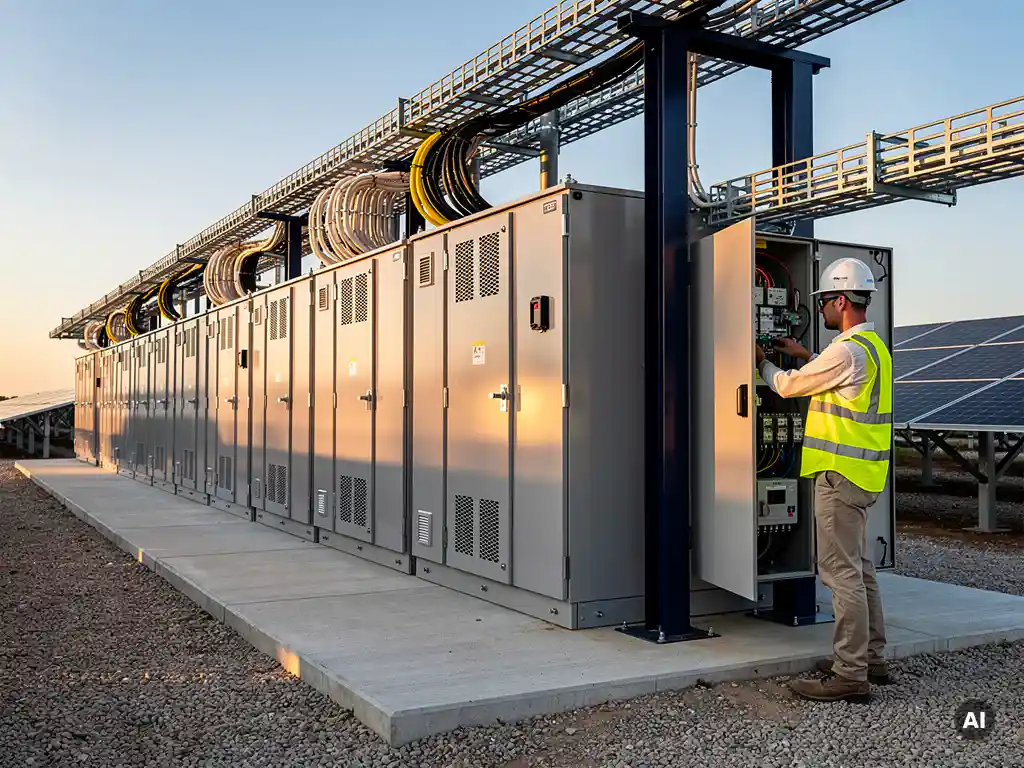
A battery energy storage system (BESS) is made up of several interconnected components: battery cells grouped into modules and racks, a battery management system (BMS), a power conversion system (PCS), a thermal management system, and an energy management system (EMS). These components work together to store electrical energy and release it on demand. Understanding how each part functions is essential for engineers designing or integrating BESS into solar projects.
How does a BESS work as a complete system?
A BESS works by converting incoming AC or DC electricity into stored chemical energy inside battery cells, then converting it back to usable electricity when needed. The system is coordinated by software layers that monitor state of charge, manage power flow, protect the hardware, and respond to grid or load signals in real time.
At the highest level, the energy management system (EMS) acts as the brain. It receives signals from the grid operator, the solar plant, or the facility load, and decides when to charge, discharge, or hold. Below that, the power conversion system handles the actual electrical conversion, while the BMS monitors every cell cluster to keep the battery operating within safe limits. Thermal management runs continuously in the background, keeping temperatures stable regardless of charge rate or ambient conditions.
In a solar-plus-storage configuration, the BESS typically absorbs excess PV generation during peak production hours and dispatches it during evening demand peaks or grid stress events. This coordination between the inverter, the PCS, and the EMS is what makes the system commercially valuable rather than just a large battery sitting on a pad.
What are the main components inside a BESS?
The main components inside a BESS are battery cells, modules, and racks; a battery management system (BMS); a power conversion system (PCS); a thermal management system; an energy management system (EMS); and the structural enclosure or container. Each component has a distinct function, and the system only performs reliably when all of them are properly integrated.
- Battery cells: The fundamental electrochemical units that store energy. Lithium iron phosphate (LFP) and nickel manganese cobalt (NMC) are the most common chemistries in commercial and utility-scale applications today.
- Modules and racks: Cells are grouped into modules for easier handling and thermal management, then stacked into racks inside a cabinet or container. The rack is the structural and electrical backbone of the battery block.
- Battery management system (BMS): Monitors voltage, current, temperature, and state of charge at the cell or module level, and enforces protection limits.
- Power conversion system (PCS): Converts DC power from the battery to AC power for the grid or load, and vice versa during charging.
- Thermal management system: Maintains operating temperature within the battery’s safe range using active cooling, heating, or both.
- Energy management system (EMS): The supervisory software layer that coordinates all other components and executes the dispatch strategy.
- Enclosure or container: Houses and protects all components, often in a standard 20-foot or 40-foot shipping container for utility-scale deployments.
What does the battery management system (BMS) do?
The battery management system (BMS) monitors and protects individual battery cells by tracking voltage, current, temperature, and state of charge in real time. It enforces safe operating limits, balances charge across cells to prevent degradation, and communicates critical data to the EMS and PCS. Without a functioning BMS, a BESS cannot operate safely.
Cell balancing is one of the BMS’s most important ongoing tasks. Because no two cells are perfectly identical, small differences in capacity and internal resistance cause some cells to charge faster or discharge deeper than others. The BMS uses passive or active balancing circuits to equalize these differences, which directly affects the long-term cycle life of the battery pack.
The BMS also enforces hard protection limits. If a cell exceeds its maximum voltage during charging, drops below its minimum voltage during discharge, or reaches a temperature threshold, the BMS triggers a protective disconnect before damage or thermal runaway can occur. This makes the BMS the primary safety layer inside any BESS, sitting between the chemistry and the rest of the electrical system.
In larger systems, a hierarchical BMS architecture is common: a cell-level BMS feeds data to a module-level BMS, which reports to a rack-level BMS, which then communicates with the EMS. This layered structure allows granular monitoring across thousands of cells without overwhelming any single controller.
What is the difference between a PCS and a standard inverter in a BESS?
A power conversion system (PCS) in a BESS is a bidirectional device that can both invert DC to AC and rectify AC to DC, allowing the battery to charge and discharge through the same unit. A standard solar inverter is unidirectional, converting DC from PV panels to AC for the grid. The bidirectionality of a PCS is what makes energy storage possible.
Beyond directionality, a PCS is designed to operate under a much wider range of DC voltage and current conditions than a standard string or central inverter. Battery voltage varies significantly depending on state of charge, and the PCS must track and respond to that variation while maintaining stable AC output. Standard PV inverters are optimized for the relatively predictable DC output of a solar array, not for the dynamic behavior of a battery pack.
A PCS also typically includes grid-forming or grid-following capabilities that go beyond what a standard inverter offers. In grid-forming mode, the PCS can establish voltage and frequency references independently, which is critical for islanding applications or microgrids where no external grid reference exists. This level of control is rarely needed in a conventional solar inverter.
In solar-plus-storage systems, the PCS and the PV inverter are sometimes combined into a hybrid inverter. However, at utility scale, they are almost always separate units, allowing each to be sized and optimized independently for its specific function.
Why is thermal management critical in a battery energy storage system?
Thermal management is critical in a BESS because lithium-ion battery cells degrade faster and become unsafe outside a narrow temperature range, typically between 15°C and 35°C for most commercial chemistries. Excess heat accelerates capacity fade and, in worst-case scenarios, can trigger thermal runaway, a self-sustaining exothermic reaction that can result in fire or explosion.
During high-rate charging or discharging, battery cells generate internal heat as a byproduct of electrochemical reactions and resistive losses. Without active cooling, this heat accumulates inside the module and rack, creating temperature gradients that cause uneven aging across cells. Cells that run hotter degrade faster, which reduces overall pack capacity and shortens the system’s useful life.
Cold temperatures present a different problem. Below roughly 0°C, lithium plating can occur during charging, where lithium ions deposit as metallic lithium on the anode rather than intercalating properly. This is irreversible and reduces capacity permanently. In cold climates, BESS installations require active heating elements to bring cells up to a safe minimum temperature before charging begins.
Modern BESS thermal management systems use liquid cooling, forced air, or a combination of both. Liquid cooling is increasingly preferred at utility scale because it offers higher heat transfer efficiency and more uniform temperature distribution across large battery racks. The thermal management system works in close coordination with the BMS, which provides real-time temperature data to trigger cooling or heating as needed.
How do BESS components differ between utility-scale and commercial projects?
At utility scale, BESS components are larger, more modular, and more redundant than in commercial installations. Utility systems use containerized battery racks, high-power PCS units rated in the megawatt range, and sophisticated EMS platforms capable of responding to grid operator dispatch signals. Commercial BESS systems use smaller, integrated cabinet-style units with simpler control interfaces suited to facility-level energy management.
Utility-scale BESS characteristics
Utility-scale systems are designed for maximum power output, long-duration discharge, and grid services such as frequency regulation, peak shaving at the transmission level, and capacity firming for large solar farms. The battery racks are housed in rows of shipping containers, each containing hundreds of kilowatt-hours of capacity. The PCS units are typically centralized, high-power converters connected to a medium-voltage transformer before reaching the grid interconnection point.
Redundancy is built into every layer. Utility systems include redundant BMS controllers, redundant cooling circuits, and often N+1 PCS configurations so that a single component failure does not take the entire system offline. The EMS at this scale integrates with SCADA systems and communicates directly with the grid operator using standardized protocols.
Commercial BESS characteristics
Commercial and industrial BESS installations, typically ranging from tens of kilowatt-hours to a few megawatt-hours, prioritize a compact footprint, simpler installation, and integration with on-site solar and load management systems. The battery, BMS, PCS, and thermal management are often pre-integrated into a single cabinet or small enclosure, reducing on-site engineering and commissioning time.
The EMS in a commercial system focuses on demand charge reduction, time-of-use optimization, and backup power rather than grid-level dispatch. Control interfaces are typically web-based dashboards rather than full SCADA environments. While the underlying electrochemistry and component functions are the same as at utility scale, the engineering complexity and redundancy requirements are substantially lower.
For solar engineers working across both project types, understanding these differences matters when sizing and specifying BESS components alongside PV system design. Tools like Virto Solar’s design platform help integrate these considerations into the broader engineering workflow, reducing the manual coordination that typically slows down projects at the design stage. If you are working on a project that includes storage integration and want to explore how software can streamline that process, get in touch with our team to discuss your specific requirements.
Frequently Asked Questions
How do I determine the right BESS size for a solar-plus-storage project?
Sizing a BESS for a solar-plus-storage project requires analyzing three key parameters: the energy capacity needed (kWh), the power rating required (kW), and the desired duration of discharge. Start by identifying the use case — whether it’s peak shaving, self-consumption optimization, or grid services — since each drives a different energy-to-power ratio. From there, model the PV generation profile against the load or dispatch schedule to find the optimal storage window. Most utility-scale projects use simulation tools to iterate through multiple scenarios before finalizing component specifications.
What is state of charge (SOC) and why does it matter for BESS operation?
State of charge (SOC) is the percentage of usable energy remaining in the battery at any given moment, analogous to a fuel gauge in a vehicle. The BMS estimates SOC continuously using a combination of current integration (coulomb counting) and voltage-based algorithms, since it cannot be measured directly. Accurate SOC estimation is critical because operating a battery too close to 0% or 100% accelerates degradation — most commercial BESS systems are configured to operate within a usable window of roughly 10–90% SOC to extend cycle life. Errors in SOC estimation can lead to premature shutdowns, reduced capacity, or accelerated aging.
What is thermal runaway and how do modern BESS designs prevent it?
Thermal runaway is a self-reinforcing chain reaction inside a battery cell where rising temperature triggers exothermic chemical reactions that generate more heat, potentially leading to fire or explosion. It can be initiated by overcharging, physical damage, internal short circuits, or extreme ambient temperatures. Modern BESS designs layer multiple safeguards against it: the BMS enforces strict voltage and temperature limits, the thermal management system actively dissipates heat, and enclosures include fire suppression systems and gas venting pathways. Cell-level fusing and module-level isolation are also standard in utility-scale designs to contain any failure before it propagates.
How does the EMS communicate with the grid operator in a utility-scale BESS?
In utility-scale deployments, the EMS communicates with the grid operator through standardized protocols such as DNP3, IEC 61850, or Modbus TCP, depending on the operator’s requirements and regional standards. The grid operator sends dispatch signals — such as charge/discharge setpoints, ramp rates, or frequency response commands — and the EMS translates these into real-time instructions for the PCS and BMS. This communication typically runs over a dedicated SCADA connection with cybersecurity protections in place. For projects participating in ancillary services markets, the EMS must also log and report performance data to verify compliance with contracted response times.
What is the typical cycle life of a lithium-ion BESS, and what factors affect it most?
Most commercial lithium-ion BESS systems are rated for 3,000 to 6,000 full charge-discharge cycles before reaching 80% of their original capacity, though LFP chemistry tends to outperform NMC at the higher end of that range. The factors that degrade cycle life fastest are chronic high temperatures, frequent deep discharges below the recommended SOC floor, high charge rates (C-rates), and poor cell balancing. Operating within the manufacturer’s recommended SOC window, maintaining stable temperatures through active thermal management, and keeping charge rates moderate can meaningfully extend the system’s useful life beyond its rated cycle count. Regular capacity testing is the most reliable way to track actual degradation over time.
Can a BESS operate independently from the grid, and what components make that possible?
Yes, a BESS can operate in island mode, disconnected from the main grid, provided the PCS supports grid-forming functionality. In grid-forming mode, the PCS establishes its own voltage and frequency reference rather than synchronizing to an external grid signal, effectively acting as the local power source. This capability is essential for microgrids, remote installations, and backup power applications. Not all PCS units support grid-forming operation — it must be explicitly specified during procurement — and the EMS must also be configured to manage load balancing and SOC within the islanded system without external dispatch signals.
What are the most common integration mistakes engineers make when adding BESS to an existing solar project?
The most frequent mistakes include undersizing the PCS relative to the peak discharge power required, failing to account for the DC voltage range mismatch between the battery and the inverter, and neglecting to specify communication protocol compatibility between the EMS and the existing plant SCADA system early in the design process. Another common oversight is not modeling the thermal environment of the installation site — a BESS container placed in a high-ambient-temperature location without adequate shading or HVAC capacity will degrade significantly faster than its rated cycle life. Engaging the BESS manufacturer’s integration team during the design phase, rather than at commissioning, prevents most of these issues.
Related Articles
This content was generated with the help of AI — it may contain mistakes
Source link