

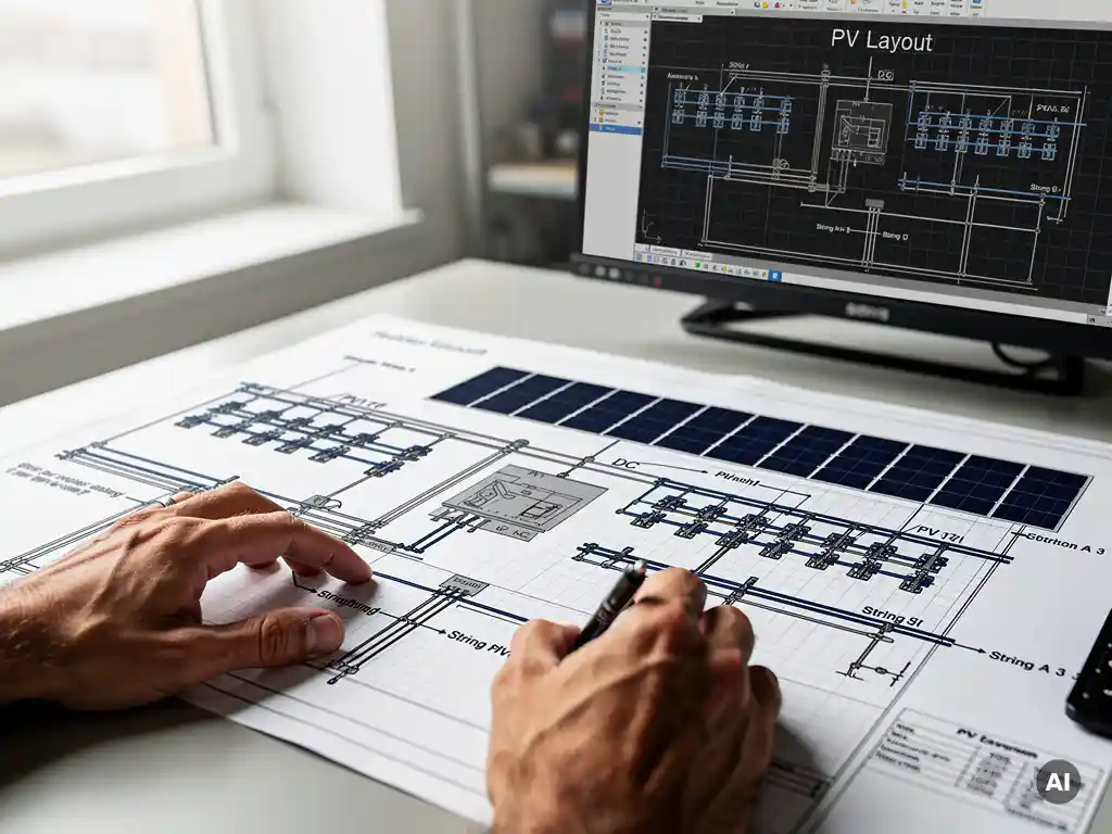
A solar wiring diagram is a visual schematic that shows how all the electrical components in a photovoltaic system are connected, including solar panels, inverters, batteries, and protection devices. It maps the physical and electrical relationships between components so that installers, engineers, and inspectors can understand, build, and verify the system safely. This article unpacks the key questions engineers and solar professionals ask about wiring diagrams, from what they show to how modern software generates them automatically.
What components does a solar wiring diagram show?
A solar wiring diagram shows every major electrical component in a PV system and the conductors that connect them. At minimum, it includes solar modules, string combiners or junction boxes, inverters, disconnect switches, overcurrent protection devices, grounding connections, and the point of connection to the grid or load. The diagram also indicates wire types, conduit runs, and conductor sizing.
Depending on the scale and type of installation, the components shown in a solar wiring diagram will vary. For a commercial rooftop system, you might see multiple string groups feeding into a combiner box before reaching a string inverter, while a utility-scale ground-mount installation often includes DC combiner boxes, central inverters, step-up transformers, and medium-voltage switchgear.
Key components typically represented include:
- PV modules arranged in strings, showing series and parallel connections
- String combiners or DC combiner boxes that aggregate multiple strings
- Inverters (string, central, or microinverters) converting DC to AC
- DC and AC disconnect switches for safe isolation
- Overcurrent protection devices such as fuses and circuit breakers
- Surge protection devices on both DC and AC sides
- Grounding and bonding conductors
- Metering equipment and the utility interconnection point
- Battery storage systems, where applicable
Each component is represented by a standardized electrical symbol, and conductors are labeled with their gauge, insulation type, and current-carrying capacity. This level of detail is what makes a wiring diagram a working engineering document rather than a conceptual sketch.
What’s the difference between a solar wiring diagram and a single-line diagram?
A solar wiring diagram shows every individual conductor and connection in the system, representing the full physical wiring layout. A single-line diagram, often called an SLD, uses a single line to represent all conductors between components, focusing on the electrical relationships and system architecture rather than the physical routing of each wire. Both documents are essential, but they serve different purposes.
Think of it this way: the wiring diagram tells an installer exactly how to wire the system in the field, while the single-line diagram gives an engineer or inspector a clear overview of the system’s electrical structure at a glance. The SLD is the document most commonly submitted for permitting and utility interconnection approval because it communicates system design efficiently without the visual complexity of every individual conductor.
When to use a wiring diagram
Wiring diagrams are most useful during installation and commissioning. They guide field crews through the physical connections, show conduit routing, and confirm that protection devices are correctly placed in the circuit. They are also valuable during troubleshooting, since they allow technicians to trace faults through the actual wiring paths.
When to use a single-line diagram
Single-line diagrams are the standard for engineering review, permitting submissions, and utility interconnection applications. Authorities having jurisdiction (AHJs) and utility engineers expect an SLD because it presents the system’s protective scheme, equipment ratings, and interconnection method in a standardized, readable format. For large commercial and utility-scale projects, the SLD is often the primary engineering deliverable alongside the layout drawings.
How do you read a solar wiring diagram?
To read a solar wiring diagram, start at the generation source (the PV modules) and follow the current path through each component toward the load or grid connection. Identify each component using its electrical symbol, check the labels on conductors for wire gauge and type, and note the ratings on protection devices. Reading a wiring diagram is a systematic process that moves from DC generation through conversion to AC distribution.
Here is a practical approach for reading a solar wiring diagram step by step:
- Identify the DC side first. Locate the PV module strings, note how many modules are in series per string, and trace the positive and negative conductors to the combiner box or directly to the inverter.
- Check string and combiner details. Look for fuse ratings in the combiner box and verify that the number of strings matches the inverter’s input specifications.
- Follow the path to the inverter. Confirm the DC disconnect is present and correctly positioned between the combiner and inverter.
- Move to the AC side. Trace the output from the inverter through the AC disconnect, overcurrent protection, and any metering equipment to the point of interconnection.
- Check grounding conductors. Verify that equipment grounding conductors are shown connecting all metal enclosures and that the grounding electrode system is indicated.
- Review conductor labels. Each wire should be labeled with its size, insulation rating, and sometimes its color code, confirming it meets the design specifications.
Familiarity with standard electrical symbols used in IEC or NEC conventions is essential for reading these diagrams accurately. Most solar wiring diagrams include a legend, so always check it before interpreting unfamiliar symbols.
What information is needed to create a solar wiring diagram?
Creating a solar wiring diagram requires detailed technical data about every component in the system, the site conditions, and the applicable electrical standards. At a minimum, you need the module specifications, inverter datasheets, cable sizing calculations, protection device ratings, and the system’s DC and AC voltage and current values. Without accurate input data, the diagram cannot be used safely for installation or permitting.
The core information required includes:
- PV module datasheet values: open-circuit voltage (Voc), short-circuit current (Isc), maximum power point voltage and current, and temperature coefficients
- String configuration: number of modules per string and number of strings per inverter input
- Inverter specifications: maximum DC input voltage, MPPT voltage range, maximum input current per MPPT, and AC output ratings
- Cable sizing calculations: conductor cross-sections based on current-carrying capacity, voltage drop limits, and installation method
- Protection device ratings: fuse and breaker ratings for both DC and AC circuits
- Grounding design: grounding electrode type and conductor sizing
- Applicable standards: IEC 62548, NEC Article 690, or local grid codes that govern equipment ratings and installation requirements
- Site-specific data: minimum and maximum ambient temperatures, which affect voltage and current calculations
Errors in any of these inputs will cascade through the diagram and potentially result in undersized conductors, incorrectly rated protection devices, or a system that fails inspection. This is why engineers traditionally spent significant time verifying each calculation before committing it to a drawing.
How does solar design software generate wiring diagrams automatically?
Solar design software generates wiring diagrams automatically by using the system’s component data and configuration to compute all electrical parameters and then produce a standardized schematic without manual drafting. The software takes the module layout, string configuration, inverter selection, and cable routing as inputs, runs the underlying calculations, and outputs a complete, code-compliant wiring diagram in a fraction of the time it would take to draw manually.
This automation matters because a wiring diagram is not just a drawing, it is the output of a chain of interdependent calculations. When module specifications change or a string is reconfigured, every conductor size, fuse rating, and voltage value in the diagram may need to be updated. Doing this manually in AutoCAD means hours of rework. Software that automates the process recalculates everything instantly and regenerates the diagram accordingly.
Our own Virto Solar platform, specifically Virto.CAD, handles this process directly within AutoCAD and BricsCAD. When engineers define the system layout and component selections, the software automatically generates single-line diagrams and wiring schematics as part of the design output, eliminating the need to redraw from scratch every time a design decision changes. This is one of the core reasons engineering teams using Virto.CAD have reduced their design time by up to 80%.
The automation workflow typically follows this sequence:
- The engineer inputs or imports the module layout and selects components from an integrated library.
- The software performs string sizing, cable sizing, and protection device calculations automatically.
- Based on those calculations, it generates the wiring diagram with correctly labeled conductors, rated protection devices, and grounding connections.
- If any input changes, the diagram updates automatically to reflect the new values.
For engineering teams working on commercial and utility-scale projects where design revisions are frequent, this kind of automation is not a convenience, it is a competitive necessity. If you want to see how automated wiring diagram generation fits into a full PV engineering workflow, get in touch with our team to explore what Virto.CAD can do for your projects.
Frequently Asked Questions
What’s the most common mistake engineers make when creating solar wiring diagrams manually?
The most common mistake is failing to account for temperature-corrected voltage and current values, which leads to undersized conductors or incorrectly rated protection devices. Engineers often use standard test condition (STC) values directly from the datasheet without applying the temperature coefficients for the site’s minimum and maximum ambient temperatures. This can result in a diagram that looks correct on paper but produces a system that trips breakers, fails inspection, or poses a safety risk in the field.
Do I need both a wiring diagram and a single-line diagram for a commercial solar project?
Yes, in most cases you will need both, and they serve distinct purposes at different stages of the project. The single-line diagram is typically required for permitting submissions and utility interconnection applications, while the detailed wiring diagram is essential for field installation and commissioning crews. Submitting only one of the two is a common cause of permit delays, so it’s worth confirming the specific documentation requirements with your local AHJ and utility before finalizing your deliverable set.
How do I know if my solar wiring diagram is code-compliant?
Code compliance depends on which standard governs your installation — primarily NEC Article 690 in the United States or IEC 62548 internationally — and whether every component rating, conductor size, and protection device shown in the diagram meets those requirements. Key checkpoints include verifying that conductor ampacity meets the 125% continuous load rule for PV source circuits, that DC disconnect ratings match the system’s maximum voltage and current, and that grounding and bonding are correctly represented. Having the diagram reviewed by a licensed electrical engineer familiar with PV systems is the most reliable way to confirm compliance before submission.
Can solar wiring diagrams be used for battery storage systems as well, or do those require separate documentation?
Solar wiring diagrams can and should include battery storage systems when they are part of the PV installation, showing the battery bank, charge controllers or hybrid inverters, and any associated protection devices as integrated elements of the overall schematic. However, battery storage systems — especially those governed by NEC Article 706 or IEC 62619 — introduce additional documentation requirements, such as battery management system (BMS) wiring and specific grounding configurations, that may need to be detailed in supplementary drawings. For larger or more complex energy storage systems, a dedicated storage wiring diagram alongside the PV schematic is often the clearest and most permitting-friendly approach.
How often should solar wiring diagrams be updated after a system is installed?
Wiring diagrams should be updated any time a physical change is made to the system, including panel replacements with a different module model, inverter upgrades, the addition of battery storage, or reconfigurations of string layouts. Keeping as-built drawings current is not just good engineering practice — many jurisdictions and utility agreements legally require that accurate documentation be maintained for the life of the system. Outdated diagrams are one of the leading causes of errors during O&M troubleshooting and can significantly slow down re-permitting processes when modifications are needed.
What’s the best way to get started with automated wiring diagram generation if my team currently drafts everything manually in AutoCAD?
The most practical starting point is to identify a mid-sized commercial project where your team is already experiencing revision-heavy design cycles, and use it as a pilot for automated tooling. Platforms like Virto.CAD integrate directly into AutoCAD and BricsCAD, meaning your team doesn’t need to abandon familiar tools or rebuild workflows from scratch — the automation layer sits on top of the environment your engineers already use. Running a parallel comparison between your manual process and the automated output on a real project is the fastest way to quantify time savings and validate diagram accuracy before rolling the approach out across your full project pipeline.
Are the electrical symbols used in solar wiring diagrams standardized across all countries?
Not entirely — there are two dominant symbol conventions used globally, IEC (International Electrotechnical Commission) and ANSI/IEEE (used predominantly in North America), and they differ in how components like transformers, switches, and protection devices are represented. Most solar wiring diagrams include a legend precisely because of this variation, and it’s important to confirm which standard your AHJ or utility expects before finalizing drawings for submission. When working on international projects, explicitly labeling the symbol standard used in the diagram title block avoids ambiguity and prevents review delays caused by unfamiliar notation.
Related Articles
This content was generated with the help of AI — it may contain mistakes
Source link